4 Specifications subject to change without notice. IM-KSAIC03-02
SYSTEM CONFIGURATION SCENARIOS
Scenario No. 1:
Match the following ductless indoor units with the corresponding
compatible SINGLE ZONE outdoor units:
• High Wall (sizes 9-36)[208-230V]
• Cassette (sizes 9-24)
• Ducted (sizes 9-24) (*refer to NOTE)
• Console (sizes 18-24)
Installation Steps:
1. Run the interconnecting piping from the indoor to the outdoor unit
using the indoor piping size.
2. Run the interconnecting wiring from the outdoor unit to the 24V
interface using terminal connections L1, L2, S and G.
3. Run the interconnecting wiring from the 24V interface to the indoor
unit using terminal connections L1, L2, S and G.
4. Run the thermostat wiring from the thermostat to the 24V interface
using connections R and C on CN15 and Y, W, G on CN19.
5. Configure the dip switches on the 24V interface accordingly.
NOTES:
Follow the Indoor and Outdoor unit's general installation
instructions.
*For the Ducted units, in order to initially setup the static
pressure, the 24V interface must be bridged. Temporarily connect
together the Communication wires L1, L2, S and G from indoor
to outdoor unit until static pressure settings are complete (see
ducted unit Installation Manual). When static pressure is
adjusted, reconnect L1, L2, S and G wires to the terminal blocks.
On selected indoor units, the Up-Down Swing Louver function as
well as the control to turn off the indoor unit display (LED) is
available on the unit’s Wireless Remote controller. The Wi-Fi
accessory and Wired Remote controller are not functional when
using the 24V interface.
For 115V Ductless applications the 24V transformer must be
replaced in the field. This is available through RCD part number
11203103000393.
Fig. 9 —Wiring Diagram
IMPORTANT: All ground wiring must be installed according to the equipment installation manual.
The indoor unit requires an updated control board for compatibility
with the 24V interface.
Refer to the Compatibility Charts on hvacpartners.com for proper
matches and serial number compatibility.
CAUTION
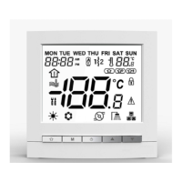
Thermostat
70
Do not
connect to
Power supply from
outdoor unit disconnect.
Two wires are line voltage
and the other is a ground wire.
*All ground wiring must be installed
according to the equipment installation manual.
*All ground wiring must be installed
according to the equipment
installation manual.

 Loading...