8 Specifications subject to change without notice. IM-KSAIC03-02
Scenario No. 4 (cont):
WIRING
All wires must be sized per NEC (National Electrical Code) or CEC
(Canadian Electrical Code) and local codes. Use Electrical Data table
MCA (minimum circuit amps) and MOCP (maximum over current
protection) to correctly size the wires and the disconnect fuse or
breakers respectively.
Per the caution note, only stranded copper conductors with a 600 volt
insulation rating wire must be used. Separate power supplies are
required for the OUTDOOR UNIT and the INDOOR UNIT.
The field supplied 14/3 stranded wire with ground and a 600 volt
insulation rating, power/communication wiring from the OUTDOOR
UNIT to 24V INTERFACE KIT consists of four (4) wires and
provides the power for the 24V Interface. Two wires are line voltage
AC power, one is communication wiring (S) and the other is a ground
wire. Wiring between the OUTDOOR UNIT to 24V INTERFACE
KIT is polarity sensitive. The use of B X wire is NOT recommended.
Auxiliary Heating: To energize an Auxiliary Heater, connect W2 on
the thermostat directly to the an electric heat relay(s) (field supplied)
and complete the circuit to the heater element(s).
The thermostat must be setup to use different heating priorities.
Key Considerations
The following steps should be taken when using this device with a
conventional central air conditioning unit:
• Indoor coil metering device (TXV/Piston) must be removed
• 24V transformer in the interface module must be disconnected
• Refrigerant charge amount may need to be adjusted, depending on
the pipe size and length, see the outdoor recharge instruction.
• The maximum air flow should not exceed 400 CFM/Ton.
When the indoor air handler or furnace has its own 24VAC
transformer, you must disconnect all four wires of the 24V Interface
kit transformer (see Fig. 13).
Fig. 13 —Wiring
Control Logic
Table 5 — Conventional Thermostat Connections
Table 6 — Mode Setting
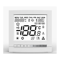
FAN SPEED - Select Auto, Low Medium or High Airflow
For Ductless Systems (Scenarios 1-3) the Fan Speed defaults to
AUTO. For Hybrid Solutions, see “Scenario No. 4:” on page 7. The
fan outputs are G1 (1st), G1+G2 (2nd), and G1+G2+G3 (3rd). For
the single fan speed only, G1 has to be connected.
Use the selection options provided to adjust the airflow supplied to
meet the individual installation needs for such things as noise,
comfort, and humidity removal.
Table 7 — Fan Speed Setting
LEGEND
The conventional thermostat must be configured for use
with a single stage air conditioner (Y output ONLY) and a
single stage heating (W) system.
CAUTION
Connector Purpose
R/C 24VAC Output
Y Cooling
W Heating
G Fan
AUX/DRY Aux/Dry Mode
Y W G Aux/Dry Setting Mode
X ☆ ☆ Cooling
X ☆ X
Heating
X X
X
Fan only
☆ ☆ OFF
X X X X OFF
X X ☆
DRY Mode (on Ductless Systems)
Unit ON/OFF G Setting Fan Speed
X Auto Fan Speed
Auto Fan Speed
X X Fan OFF
ON
X OFF
☆ ON or OFF
Only the approved combinations and model numbers of the fan coils
listed on the Appendix shall be used to avoid any damages to the fan
motor.
The use of a fan coils with a PSC motor is not recommended or
approved.
CAUTION

 Loading...