Specifications are subject to change without notice.
21441 01 3400 02
A190032
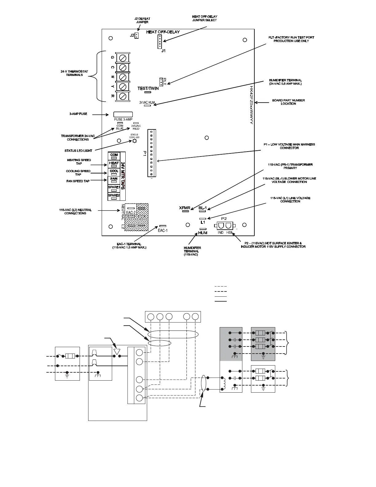
Fig. 24 -- Furnace Control
Representative drawing only, some models may vary.
115-V FIELD-
SUPPLIED
DISCONNECT
AUXILIARY
J-BOX
24-V
TERMINAL
BLOCK
THREE-WIRE
HEATING-ONLY
FIVE WIRE
NOTE 1
NOTE 2
FIELD-SUPPLIED
DISCONNECT
CONDENSING
UNIT
TWO
WIRE
FURNACE
C
O
N
T
R
O
L
R
G
COM
WCR GY
GND
GND
FIELD 24-V WIRING
FIELD 115-, 208/230-, 460-V WIRING
FACTORY 24-V WIRING
FACTORY 115-V WIRING
208/230- OR
460-V
THREE
PHASE
208/230-V
SINGLE
PHASE
BLOWER DOOR SWITCH
WHT
BLK
WHT
BLK
NOTES: Connect Y-terminal in furnace as shown for proper blower operation.
Some thermostats require a "C" terminal connection as shown.
If any of the original wire, as supplied, must be replaced, use
m
r
iv
l
n
wir
.
W
Y
GND
THERMOSTAT
TERMINALS
1.
2.
3.
A190079
Fig. 25 -- Heating and Cooling Application Wiring Diagram with 1--Stage Thermostat
 Loading...