Specifications are subject to change without notice.
20
441 01 3400 02
NOTE: The J--Box cover need not be removed from the J--Box
in order to move the J-- Box. Do NOT remove green ground
screw inside J--Box.
2. Cut wire tie on loop in furnace wires attached to J--box.
3. Move J-- Box to desired location.
4. Fasten J--Box to casing with two screws removed in Step 1.
5. Route J--Box wires within furnace away from sharp edges,
rotating parts and hot surfaces.
ELECTRICAL CONNECTION TO J--BOX
Electrical Box on Furnace Casing Side
FIRE OR ELECTRICAL SHOCK HAZARD
Failure to follow this warning could result in personal
injury, death, or property damage.
If field -- supplied manual disconnect switch is to be mounted
on furnace casing side, select a location where a drill or
fastener cannot damage electrical or gas components.
!
WARNING
1. Select and remove a hole knockout in the casing where the
electrical box is to be installed.
NOTE: Check that duct on side of furnace will not interfere with
installed electrical box.
2. Remove the desired electrical box hole knockout and posi-
tion the hole in the electrical box over the hole in the fur-
nace casing.
3. Fasten the electrical box to casing by driving two field
supplied screws from inside electrical box into casing
steel.
4. Remove and save two screws holding J--Box.
5. Pull furnace power wires out of 1/2 -- in. (12 mm) diameter
hole in J--Box. Do not loosen wires from strain-- relief
wire--tie on outside of J--Box.
6. Route furnace power wires through holes in casing and
electrical box and into electrical box.
7. Pull field power wires into electrical box.
8. Remove cover from furnace J-- Box.
9. Route field ground wire through holes in electrical box
and casing, and into furnace J-- Box.
10. Reattach furnace J--Box to furnace casing with screws re-
movedinStep4.
11. Secure field ground wire to J--Box green ground screw.
12. Complete electrical box wiring and installation. Connect
line voltage leads as shown in Fig. 25. Use best practices
(NEC in U.S. for wire bushings, strain relief, etc.)
13. Reinstall cover to J -- Box. Do not pinch wires between
cover and bracket.
POWER CORD INSTALLATION IN FURNACE
J--BOX
NOTE: Power cords must be able to handle the electrical
requirements listed in Table 7. Refer to power cord
manufacturer’s listings.
1. Remove cover from J -- Box.
2. Route listed power cord through 7/8--in. (22 mm) diameter
hole in J--Box.
3. Secure power cord to J--Box bracket with a strain relief
bushing or a connector approved for the type of cord used.
4. Secure field ground wire to green ground screw on J--Box
bracket.
5. Connect line voltage leads as shown in Fig. 25.
6. Reinstall cover to J -- Box. Do not pinch wires between
cover and bracket.
BX CABLE INSTALLATION IN FURNACE
J--BOX
1. Remove cover from J -- Box.
2. Route BX cable into 7/8-- inch diameter hole in J--Box.
3. Secure BX cable to J--Box bracket with connectors ap-
proved for the type of cable used.
4. Secure field ground wire to green ground screw on J--Box
bracket.
5. Connect line voltage leads as shown in Fig. 25.
6. Reinstall cover to J -- Box. Do not pinch wires between
cover and bracket.
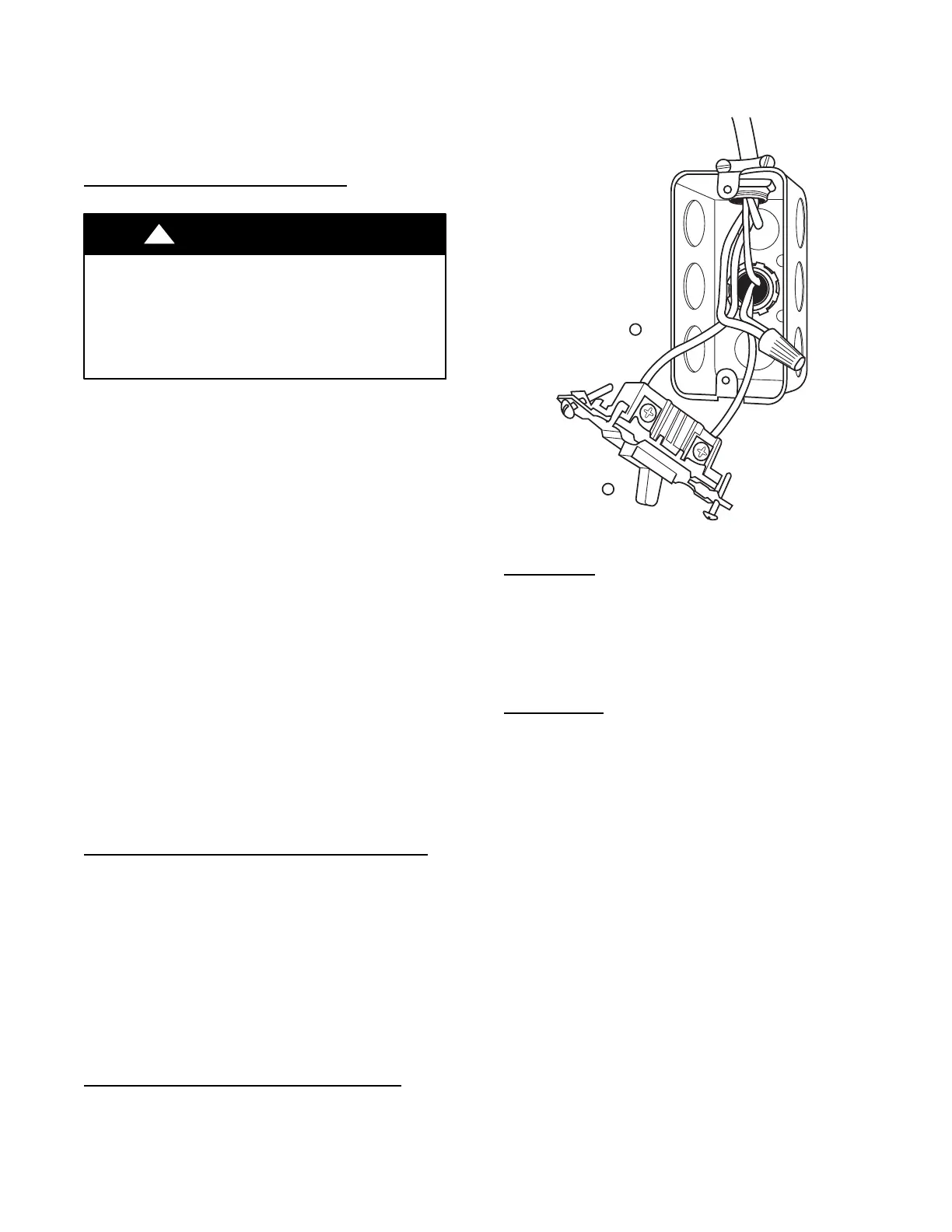
A10141
Fig. 23 -- Field--Supplied Electrical Box on Furnace Casing
24--V
WIRING
Ma ke field 24--v connec t ions at the 24--v t erminal st ri p. (See Fig.
25.) Conne ct ter m ina l Y as shown in Fi g. 24 for pr oper c ooli ng
opera tion. Use only AWG No. 18, color--coded, copper ther m ostat
wir e .
The 24--v circuit contains an automotive--type, 3--amp. fuse located
on the control. Any direct shorts during installation, service, or
maintenance could cause this fuse to blow . If fuse replacement is
requi r ed, use ONLY a 3--amp. fuse of i dentic al si ze.
ACCESSORIES
1. Electronic Air Cleaner (EAC)
Connect an accessory Electronic Air Cleaner (if used) using
1/4--in female quick connect terminals to the two male 1/4--in
quick--connect te rmi nals on the contr ol board marke d
EAC--1 and EAC--2. The terminals are rated for 115 VAC,
1.0 amps maxi m um and ar e energiz ed during blowe r motor
opera t ion. (See Fig. 24.)
2. Humidifier (HUM)
S a. 24VAC HUM: Connect an accessory 24 VAC, 0.5
amp maximum humidifier (if used) to the 1/4-- in male
quick--connect 24VAC HUM terminal and C screw
terminal on the control board thermostat strip. The
24VAC HUM terminal is energized when there is a call
for heat (W) and the pressure switch (PRS) closes. (See
Fig. 24 and 48).
S b. HUM: Connect an accessory 115VAC (EAC and
HUM are 1 amp maximum combined) humidifier (if
used) to the ¼--inch male quick connect HUM terminal
and EAC--2 ¼--inch quick connect. The HUM terminal
is energized when the inducer motor is energized
(IDR). (See Fig. 24 and 48).
NOTE: A field--supplied, 115--v controlled relay connected to
EAC terminals may be added if humidifier operation is desired
during blower operation.
NOTE: DO NOT connect furnace control 24VAC HUM
terminal to H (humidifier) terminal on humidity sensing
thermostat, or similar device. See humidity sensing thermostat,
thermostat, or controller manufacturer’s instructions for proper
connection.
 Loading...