4
LEGEND
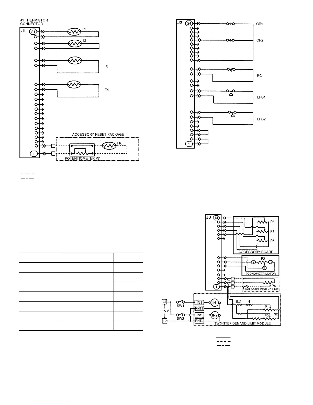
Fig. 2 — Pin Terminal Connector J1
Thermistor Inputs
T—
Thermistor
Field Wiring
Accessory
LEGEND
Fig. 3 — Pin Terminal Connector J2
Status Switch Inputs
CR —
Control Relay
EC —
Enthalpy Control
LPS —
Low-Pressure Switch
Table 2 — Pin Terminal Connector J2
Status Switch Inputs
LEGEND
NOTE: Terminal numbers 5, 6, 11, 12, 16-19, and 21-23 are not used
on these units.
CONNECTOR J2
TERMINAL NO.
STATUS SWITCH
UNIT SIZE
034-104
1,2
Oil Pressure,
Circuit 2
Jumpered
3,4
Oil Pressure,
Circuit 1
Jumpered
7,8
Loss of Charge,
Circuit 2
LPS2
9,10
Loss of Charge,
Circuit 1
LPS1
13,14
Economizer
Changeover
EC
15,20
Compressor Fault
Signal
CR2
15,24
Compressor Fault
Signal
CR1
CR —
Control Relay
EC —
Enthalpy Control
LPS —
Low-Pressure Switch
LEGEND
Fig. 4 — Pin Terminal Connector J3
Potentiometer Inputs
IN —
Input Factory Wiring
P—
Potentiometer Field Wiring
RNT —
Return Accessory
SW —
Switch