EasyManua.ls Logo

Carrier Performance 24APA User Manual

Carrier Performance 24APA
18 pages
To Next Page IconTo Next Page
Page #1 background imageLoading...
Page #1 background image
Installation Instructions
24APA
Performancet Series Air Conditioner
with Puronr Refrigerant
1---1/2 to 5 Nominal Tons (Size 18 To 60)
the environmentally sound refrigerant
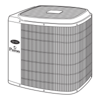
Fig. 1 --- 24APA
NOTE: Read the entire instruction manual before starting the
installation.
TABLE OF CONTENTS
PAGE
SAFETY CONSIDERATIONS 2......................
INSTALLATION RECOMMENDATIONS 2............
INSTALLATION 3--9,14............................
Step 1 -- Check Equipment & Jobsite 3................
Step 2 -- Install on Solid Pad 3......................
Step 3 -- Clearance Requirements 3...................
Step 4 -- Operating Ambient 3.......................
Step 5 -- Install TXV 3 -- 4.........................
Step 6 -- Make Piping Connections 5 -- 7..............
Step 7 -- Make Electrical Connections 7 -- 8............
Step 8 -- Compressor Crankcase Heater 8..............
Step 9 -- Install Electrical Accessories 8..............
Step 10-- Check OCT and OAT Thermistor Attachment 8..
Step 11 -- Start--Up 8 -- 9...........................
Step 12 -- Check Charge 9, 14.......................
GENERAL SEQUENCE OF OPERATION 9............
CONTROL FUNCTIONS
AND SEQUENCE OF OPERATION 10 -- 11.............
TROUBLESHOOTING 11 -- 12........................
FINAL CHECKS 13.................................
CARE AND MAINTENANCE 13......................
SUBCOOLING TABLE 14............................
24 VOLT CONNECTION DIAGRAMS 15 -- 16...........
PURONR REFRIGERANT QUICK REF. GUIDE 17.....
Questions and Answers:

Carrier Performance 24APA Specifications

General IconGeneral
Model24APA
RefrigerantR-410A
Cooling Stages1
Sound Level (Outdoor)As low as 72 dB
ENERGY STAR CertifiedYes
Operating Voltage208/230 V
Phase1
TypeAir Conditioner
Compressor TypeSingle-Stage
Sound Level (Indoor)Not Available
HSPFNot Applicable

Summary

SAFETY CONSIDERATIONS

INSTALLATION RECOMMENDATIONS

Guidelines for optimal unit placement and vibration isolation for quiet operation.

CRITICAL SAFETY WARNINGS

Crucial warnings about electrical shock, unit operation, and refrigerant handling.

INSTALLATION: INITIAL SETUP

EQUIPMENT CHECK AND PAD INSTALLATION

Verifying equipment and selecting a solid pad for unit mounting.

CLEARANCES AND OPERATING AMBIENT

Setting required clearances and noting operating ambient temperature limits.

TXV INSTALLATION

Procedure for installing the thermostatic expansion valve (TXV).

INSTALLATION: TXV REPLACEMENT

TXV INSTALLATION IN PLACE OF PISTON

Detailed guide for replacing a piston with a TXV in older indoor coils.

TXV REPLACEMENT ON R-22 INDOOR COILS

Detailed guide for replacing an R-22 TXV with a Puron TXV.

INSTALLATION: PIPING AND ACCESSORIES

REFRIGERANT PIPING CONNECTIONS

Instructions for connecting refrigerant lines, including tube diameter recommendations.

REFRIGERANT AND ACCESSORY TABLES

Tables detailing refrigerant tube sizes and accessory requirements for various applications.

INSTALLATION: TUBING AND EVACUATION

LIQUID LINE FILTER DRIER INSTALLATION

Procedure for installing the mandatory liquid line filter drier.

REFRIGERANT TUBING EVACUATION

Methods for deep vacuum evacuation to remove contaminants.

INSTALLATION: EVACUATION AND ELECTRICAL

TRIPLE EVACUATION METHOD

Alternative evacuation procedure using dry nitrogen.

ELECTRICAL CONNECTIONS

Guidance on routing and connecting power and ground wires.

INSTALLATION: COMPONENT CHECKS AND START-UP

COMPONENT INSTALLATION AND CHECKS

Covers crankcase heater, accessories, and thermistor attachments.

SYSTEM START-UP NOTES

Important safety and operational notes before starting the unit.

SYSTEM START-UP AND CHARGING

SYSTEM START-UP PROCEDURE

Steps for safely energizing the system and initial operation.

CHECK REFRIGERANT CHARGE (COOLING)

Detailed procedure for verifying refrigerant charge using subcooling.

CONTROL FUNCTIONS AND OPERATION

COOLING OPERATION AND STATUS LIGHTS

Describes cooling mode operation and diagnostic indicator lights.

CRANKCASE HEATER AND FAN OPERATION

Explains operation of the crankcase heater and outdoor fan motor.

TIME DELAYS AND UTILITY INTERFACE

Details operational time delays and utility control input.

LOW AMBIENT COOLING OPERATION

Requirements and operation for cooling below 55°F.

TROUBLESHOOTING COMMON ISSUES

COMMUNICATION AND PRESSURE SWITCH PROBLEMS

Diagnosing and resolving communication failures and pressure switch trips.

CONTROL, VOLTAGE, AND COMPRESSOR FAULTS

Troubleshooting control board, voltage, compressor thermal, and contactor issues.

TEMPERATURE THERMISTOR FAULTS

Identifying and addressing issues with outdoor air and coil temperature sensors.

STATUS CODES AND DIAGNOSTICS

AMBER LED FLASH CODES INTERPRETATION

Interpreting status codes flashed by the amber LED for fault diagnosis.

STATUS CODE REFERENCE TABLE

A comprehensive list of fault codes, their meanings, and possible actions.

FINAL CHECKS AND MAINTENANCE

FINAL INSTALLATION CHECKS

Verifying wiring, tubing security, and valve stem tightness before handover.

CARE AND MAINTENANCE GUIDELINES

Recommendations for periodic maintenance to ensure optimal performance.

REFRIGERANT CHARGING DATA

LIQUID-LINE TEMPERATURE TABLE

Correlates liquid service valve pressure with required subcooling temperature.

WIRING DIAGRAMS

INFINITY CONTROL WIRING

Diagrams for connecting the Infinity Control system, including OAT sensor.

STANDARD THERMOSTAT WIRING

Diagrams for 3-wire and 2-wire thermostat connections to various units.

WIRING DIAGRAMS

2-WIRE NON-COMMUNICATING THERMOSTAT CONNECTIONS

Wiring diagram for 2-wire thermostat use with specific serial number ranges.

REFRIGERANT QUICK REFERENCE GUIDE

PURON® (R-410A) GUIDE

Essential information on Puron refrigerant, equipment, and safety practices.

Related product manuals