© 2024 Carrier. All rights reserved.
Edition Date: 06/24
Catalog No: 26SPA6-1SI
Replaces:New
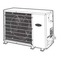
26SPA6: Installation Instructions
Manufacturer reserves the right to change, at any time, specifications and designs without notice and without obligations.
8
Final Checks
IMPORTANT: Before leaving job, be sure to do the following:
1. Ensure that all wiring is routed away from tubing and sheet metal
edges to prevent rub-through or wire pinching.
2. Ensure that all wiring and tubing is secure in unit before adding
panels and covers. Securely fasten all panels and covers.
3. Tighten service valve stem caps to 1/12-turn past finger tight.
4. Leave Owner’s Manual with owner. Explain system operation and
periodic maintenance requirements outlined in manual.
5. Fill out Dealer Installation Checklist and place in customer file.
Repairing Refrigerant Circuit
When breaking into the refrigerant circuit to make repairs, or for any
other purpose, the following procedures shall be used.
1. Safely remove the refrigerant using a recovery pump certified for
flammable refrigerants.
2. Purge the refrigerant circuit with nitrogen gas.
3. Evacuate the refrigerant circuit to 1500 microns.
4. Break vacuum with a nitrogen purge of the refrigerant circuit
ensuring that the outlet of the vacuum pump is not near a potential
ignition source.
5. Open the circuit by cutting or brazing.
CARE AND MAINTENANCE
For continuing high performance and to minimize possible equipment
failure, periodic maintenance must be performed on this equipment.
Frequency of maintenance may vary depending upon geographic areas,
such as coastal applications. See Owner’s Manual for information.
Training
My Learning Center is your central location for professional residential HVAC training resources that help strengthen careers and businesses. We
believe in providing high quality learning experiences both online and in the classroom.
Access My Learning Center with your HVACpartners credentials at www.mlctraining.com. Please contact us at mylearning@carrier.com with
questions.
Table 3 – Required Liquid Line Temperature
Liquid (PSIG)
Pressure at
Service Valve
R-454B Required Subcooling Temperature (°F)
6 8 10 12 14 16
238 78 76 74 72 70 68
245 80 78 76 74 72 70
252 82 80 78 76 74 72
260 84 82 80 78 76 74
268 86 84 82 80 78 76
276 88 86 84 82 80 78
284 90 88 86 84 82 80
292 92 90 88 86 84 82
301 94 92 90 88 86 84
309 96 94 92 90 88 86
318 98 96 94 92 90 88
327 100 98 96 94 92 90
336 102 100 98 96 94 92
346 104 102 100 98 96 94
355 106 104 102 100 98 96
365 108 106 104 102 100 98
375 110 108 106 104 102 100
385 112 110 108 106 104 102
396 114 112 110 108 106 104
406 116 114 112 110 108 106
417 118 116 114 112 110 108
428 120 118 116 114 112 110
439 122 120 118 116 114 112
450 124 122 120 118 116 114