10 Specifications subject to change without notice. IM-40MBDQ-05
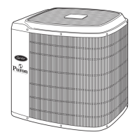
RETURN AIR ARRANGEMENT (SIZES 09K-48K ONLY)
Based on the return air conditions in the field, the factory
configured rear return arrangement of the unit may be modified
to allow bottom return.
To modify:
1. Remove the Air Inlet Flange/filter rack and ventilation panel.
Fig. 19 — Remove the Air Inlet Flange
2. Install the seal on the bottom inlet.
3. Swap the position to change the rear return to a bottom return
arrangement installing the Air Inlet flange and the filters.
Fig. 20 — Change the Rear Return
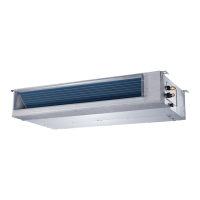
4. Install the filter brackets to lock the filter in place.
Fig. 21 — Install the Filter Brackets
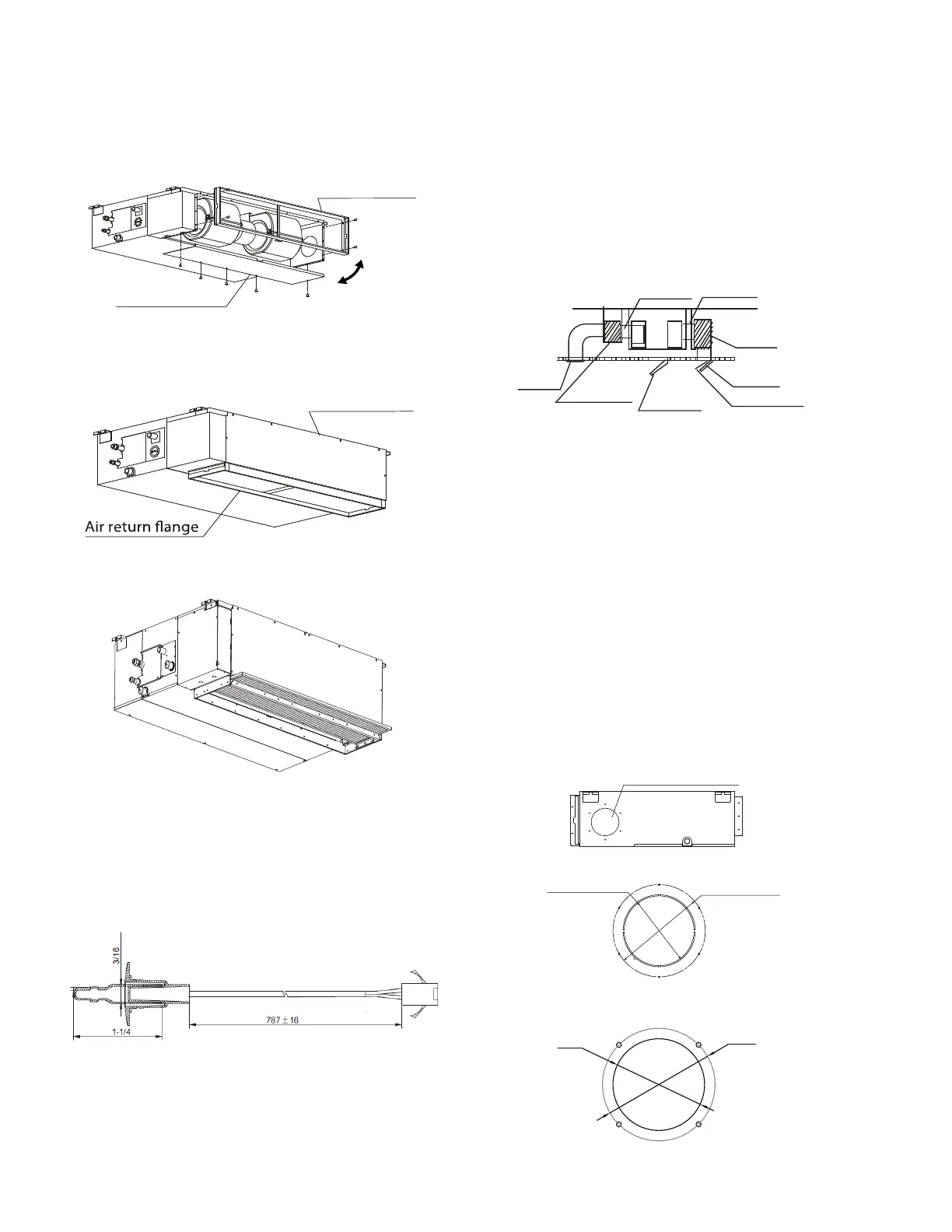
Return Temperature Sensor
- A button sensor (
p/n
40VM900009 - sold separately)
may be used for situations where
a indoor ducted unit is reading an inaccurate room temperature
due to installation factors. The button sensor kit has a length of
66ft (20m). Replace the factory T1 sensor, which can be found
inside the indoor unit. The sensor may be installed on the wall or
ceiling. Airflow must be considered for accurate sampling.
Fig. 22 — Button Sensor
NOTE: A temperature compensation correction may be
necessary depending on the installation location of the unit.
Consult the wireless remote controller’s service manual for
advanced steps on temperature compensation.
Step 3 - Installing Ductwork
Connect the return and supply air ducts to the ducts over the
outside flanges provided on the unit. Secure the canvas tie to
the indoor unit's flange, using the proper fasteners for the type
of duct used and the seal duct-to-unit joint. Use canvas duct
(flexible connectors) between the ductwork and the unit to
prevent transmission of vibration.
Maintain an adequate distance between the return and supply
diffusers to avoid short circulation of air within the space. The
filter is located on the return side of the unit, on the rear or
bottom depending on the return air inlet arrangement.
Fig. 23 — Installing Duct
OUTSIDE AIR CONNECTION
If needed, a knockout for the outside air duct connection is
located on the side of the unit downstream of the air filter.
Follow the recommendation to field supply and field install a
booster fan on the duct work used for outside air. A relay to
energize a booster fan may be powered by the connection on
the PCB board CN43. This connection is 230 volt AC and
rated for 200 watts.
NOTE: The manufacturer recommends NOT powering the fan
motor by this circuit.
The output of the NEW FAN (CN43) is powered
ON
while the
indoor fan is active.
NOTE: The amount of outside air is dependent upon different
factors such as the booster fan, outside air duct work type and
length, static pressure, etc. Refer to the local IAQ
specifications for the outdoor air quantities and control.
Fig. 24 — Outside Air Connection Sizes 18K-58K
Fig. 25 — Outside Air Connection Sizes 09K-12K
Air inlet ange
Canvas tie-in Canvas tie-in
Air outlet
Supply Plenum
Return Plenum
Access Panel
Air inlet
Air lter
Ø92mm(3.62”)
Ø113mm(4.45”)
 Loading...