16 Specifications subject to change without notice. IM-40MBDQ-05
ELECTRICAL DATA
Table 9 — Electrical Data
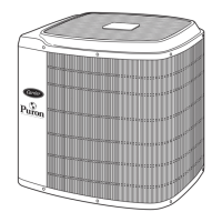
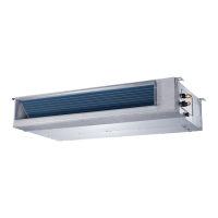
CONNECTION DIAGRAMS
Fig. 43 — Connection Diagrams (sizes 09K to 24K)
Fig. 44 — Connection Diagrams (sizes 36K and 58K)
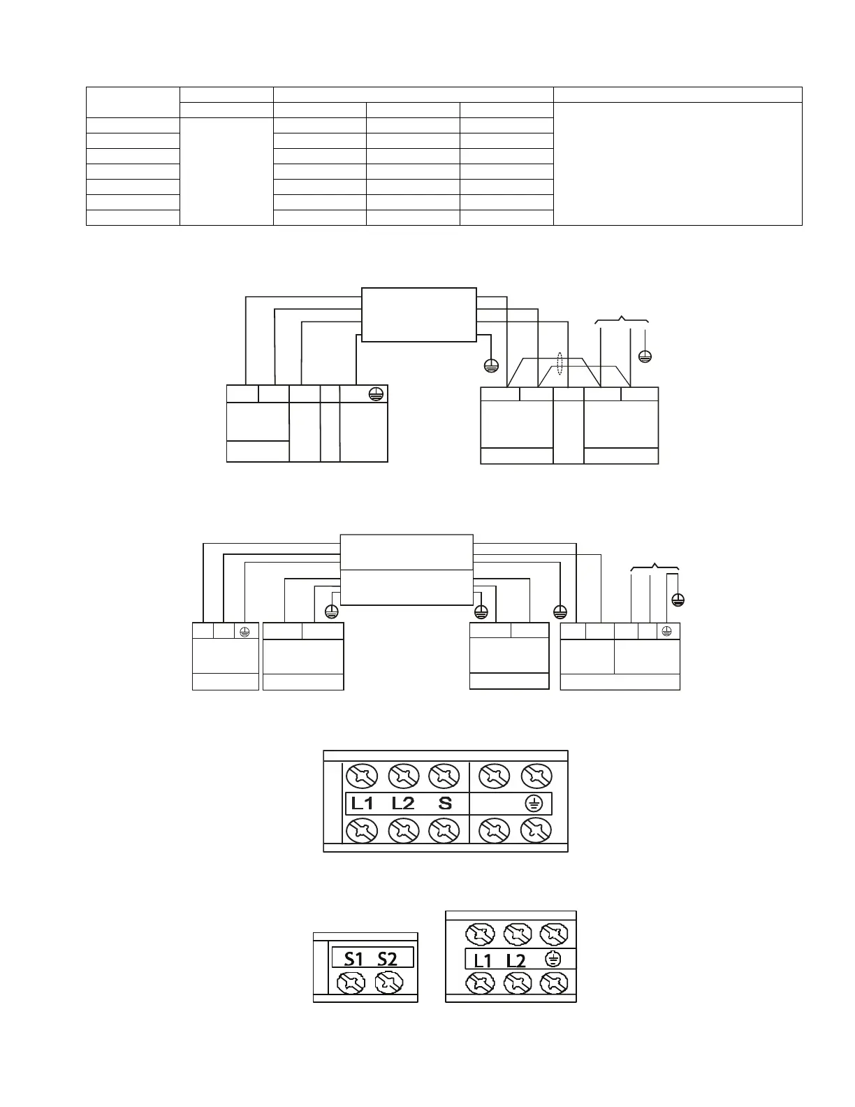
Fig. 45 — Control and Power Terminal on Indoor Unit (sizes 09K to 24K)
Fig. 46 — Control and Power Terminals on Indoor Unit (sizes 36K to 58K)
UNIT SIZE
INDOOR FAN MAX FUSE CB AMP
V-PH-HZ FLA HP W
Refer to outdoor unit installation instructions –
Indoor unit powered by the outdoor unit
09
208-230/1/60
1.11 0.18 130
12 1.11 0.18 130
18 1.2 0.27 200
24 1.2 0.27 200
36 2.45 0.56 420
48 3.2 0.75 560
58 3.65 0.952 1,000
208-230-1-60
208-230-1-60
L2
S
L1
L2
CONNECTING CABLE
OUTDOOR TO INDOOR
Indoor Unit
Power Supply
208-230-1-60
Indoor
Signal
High
GND
Ground
Power to
Indoor Unit
208-230-1-60
Y
Voltage
Indoor
Signal
High
Voltage
208-230-1-60
L1
L2
FIELD POWER SUPPLY
Indoor Unit
Power Supply
Low voltage
Nonpolar RS-485
communication
208-230-1-60
Nonpolar RS-485
Low voltage
communication
Outdoor Unit
208-230-1-60
Power Supply
SHIELDED WIRE CONNECTING
OUTDOOR TO INDOOR
To Indoor Unit
Power Supply
S1
S2
L1
(1)L1
(2)L2
L2
P(S1)
GND
Q(S2)
CONNECTING CABLE
OUTDOOR TO INDOOR
 Loading...