IM-40MBDQ-05 Specifications subject to change without notice. 7
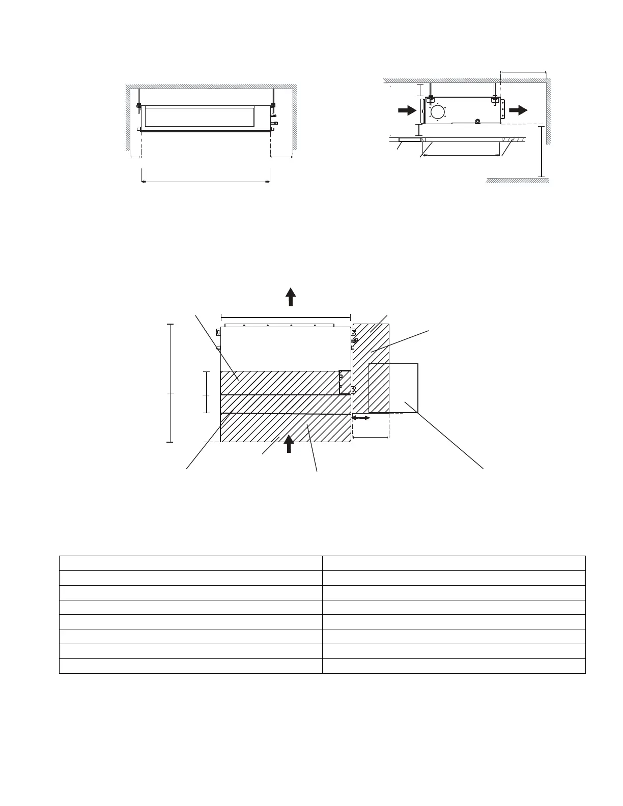
INSTALLATION CLEARANCES HORIZONTAL INSTALLATIONS
Fig. 7 — Installation Clearances
MAINTENANCE CLEARANCES
Provide a service access for inspection purposes.
Fig. 8 — Maintenance Clearances
Table 5 — Maintenance Clearances
NOTE: If installed above a fixed ceiling, utilize a ceiling access panel the length and width of the unit, otherwise the
blower components and/or entire unit cannot be removed.
If a single access panel is desired, the minimum dimensions should be:
• Single Access Panel Width: The width of the unit plus 2-inches on both sides
• Single Access Panel Length: The length of the unit plus 18-inches on the connection end and 2-inches on the opposite end.
CAPACITY (KBTU) B
9K 11.81in.(30cm)
12K 11.81in.(30cm)
18K 11.81in.(30cm)
24K 11.81in.(30cm)
36K 11.81in.(30cm)
48K 15.75in.(40cm)
58K 15.75in.(40cm)
Left
side
Right
side
Strong and durable ceiling
Indoor unit
)mc03(ni8.11> )mc01(ni4>
>0.8in(2cm)
>
0.8in(2cm)
>
11.8in(30cm)
(ni2.8 >)mc052
Floor
Service access Ceiling
( When there is no ceiling)
Ceiling opening size
Access Panel Ceiling opening size
>11.8in(30cm)
Service access
Service access
Unit
Unit width
Coil Connection Area
Condensate Drain Piping Area
Condensate Pump Service Clearance
Sensor Service Clearance
B
tinu fo htpeD
Access Panel
17.7 in (45cm) x 17.7 in (45cm)
7.8 in (20cm)
)mc03( ni 18.11>
)mc01( ni 4>
Bottom Return
Bl
ower/Motor Service Clearance
Filter Service Clearance
Blower/Motor Service Clearance
PCB Board Service Clearance
 Loading...