Installation Instructions
NOTE: Read the entire instruction manual before starting the installation.
Safety Considerations
Improper installation, adjustment, alteration, service, maintenance, or
use can cause explosion, fire, electrical shock, or other conditions which
may cause death, personal injury or property damage. Consult a
qualified installer, service agency, or your distributor or branch for
information or assistance. The qualified installer or agency must use
factory-authorized kits or accessories when modifying this product.
Refer to the individual instructions packaged with kits or accessories
when installing.
Follow all safety codes. Wear safety glasses, protective clothing and
work gloves. Have a fire extinguisher available. Read these instructions
thoroughly and follow all warnings or cautions included in literature and
attached to the unit. Consult local building codes and the current editions
of the National Electrical Code (NEC) NFPA 70.
In Canada, refer to the current editions of the Canadian Electrical Code
CSA C22.1.
Recognize safety information. This is the safety-alert symbol . When
you see this symbol on the unit and in instruction manuals, be alert to the
potential for personal injury.
Understand the signal words DANGER, WARNING, and CAUTION.
These words are used with the safety-alert symbol. DANGER identifies
the most serious hazards which will result in severe personal injury or
death. WARNING signifies hazards which could result in personal
injury or death. CAUTION is used to identify unsafe practices which
may result in minor personal injury or product and property damage.
NOTE is used to highlight suggestions which will result in enhanced
installation, reliability, or operation.
Table of Contents
Safety Considerations . . . . . . . . . . . . . . . . . . . . . . . . . . . . . . . . . . . . . . . 1
Table of Contents . . . . . . . . . . . . . . . . . . . . . . . . . . . . . . . . . . . . . . . . . . 1
Introduction. . . . . . . . . . . . . . . . . . . . . . . . . . . . . . . . . . . . . . . . . . . . . . . 1
Heater Packages . . . . . . . . . . . . . . . . . . . . . . . . . . . . . . . . . . . . . . . . . . . 1
Installation . . . . . . . . . . . . . . . . . . . . . . . . . . . . . . . . . . . . . . . . . . . . . . . 2
Air Ducts. . . . . . . . . . . . . . . . . . . . . . . . . . . . . . . . . . . . . . . . . . . . . . . . . 5
Electrical Connections . . . . . . . . . . . . . . . . . . . . . . . . . . . . . . . . . . . . . . 5
Table 1 – Fan Speed Selection . . . . . . . . . . . . . . . . . . . . . . . . . . . . . . 7
Refrigerant Tubing Connection and Evacuation . . . . . . . . . . . . . . . . . . 7
Refrigerant Flow-Control Device. . . . . . . . . . . . . . . . . . . . . . . . . . . . . . 7
Condensate Drains . . . . . . . . . . . . . . . . . . . . . . . . . . . . . . . . . . . . . . . . . 7
Accessories . . . . . . . . . . . . . . . . . . . . . . . . . . . . . . . . . . . . . . . . . . . . . . . 8
Sequence of Operation . . . . . . . . . . . . . . . . . . . . . . . . . . . . . . . . . . . . . . 8
Start-Up Procedures . . . . . . . . . . . . . . . . . . . . . . . . . . . . . . . . . . . . . . . . 9
Care and Maintenance . . . . . . . . . . . . . . . . . . . . . . . . . . . . . . . . . . . . . . 9
Table 2 – Air Delivery Performance Correction Component Pressure
Drop (in. wc) at Indicated Airflow (Dry-to-Wet Coil) . . . . . . . . . . . . 9
Table 3 – Factory-Installed Filter Static Pressure Drop (in. wc) . . . . 9
Table 4 – Electric Heater Static Pressure Drop (in. wc). . . . . . . . . . 10
Table 5 – PF4MNP Airflow Performance (CFM) . . . . . . . . . . . . . . 10
Table 6 – PF4MNB Airflow Performance (CFM) . . . . . . . . . . . . . . 11
Introduction
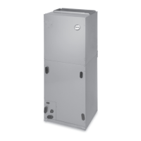
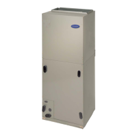
PF4M models are R-410A Fan Coils designed for installation flexibility.
These units leave the factory compliant with low leak requirements of
less than 2% cabinet leakage rate at 0.5 inches W.C. and 1.4% cabinet
leakage rate at 0.5 inches W.C. when tested in accordance with
ASHRAE 193 standard.
A TXV is used on PF4MNP (018–060) and PF4MNB(019–061). All
these fan coils use a multi-tap ECM motor for efficiency. The units have
be designed for upflow, downflow (kit required), and horizontal
orientations, including manufactured and mobile home applications.
These units require a field supplied air filter, and are designed
specifically for R-410A refrigerant air conditioners and heat pumps as
shipped. These units are available for systems of 18,000 through 60,000
BTUh nominal cooling capacity. Factory- authorized, field - installed
electric heater packages are available in sizes 5 through 30kW. See
Product Data literature for all available accessory kits.
Heater Packages
This unit may or may not be equipped with an electric heater package.
For units not equipped with factory-installed heat, a factory-approved,
field-installed, UL listed heater package is available from your
equipment supplier. See unit rating plate for a list of factory-approved
heaters. Heaters that are not factory approved could cause damage which
would not be covered under the equipment warranty. If fan coil contains
a factory-installed heater package, minimum circuit ampacity (MCA)
and maximum fuse/breaker may be different than units with a same size
field-installed accessory heater. The differences is not an error and is due
to calculation difference per UL guidelines.
PF4MNB, PF4MNP
FAN COIL UNITS
SIZES 018 TO 061
WARNING
!
ELECTRICAL OPERATION HAZARD
Failure to maintain proper clearances could result in personal injury or
death.
Before installing or servicing unit, always turn off all power to unit.
There may be more than 1 disconnect switch. Turn off accessory heater
power if applicable.
CAUTION
!
CUT HAZARD
Failure to follow this caution may result in personal injury.
Sheet metal parts may have sharp edges or burrs. Use care and wear
appropriate protective clothing, safety glasses and gloves when
handling parts.