EasyManua.ls Logo

Carrier PF4MNA - User Manual

Carrier PF4MNA
11 pages
Print Icon
To Next Page IconTo Next Page
Loading...
Installation Instructions
NOTE: Read the entire instruction manual before starting the installation.
SAFETY CONSIDERATIONS
Improper installation, adjustment, alteration, service, maintenance, or
use can cause explosion, fire, electrical shock, or other conditions which
may cause death, personal injury or property damage. Consult a
qualified installer, service agency, or your distributor or branch for
information or assistance. The qualified installer or agency must use
factory-authorized kits or accessories when modifying this product.
Refer to the individual instructions packaged with kits or accessories
when installing.
Follow all safety codes. Wear safety glasses, protective clothing and
work gloves. Have a fire extinguisher available. Read these instructions
thoroughly and follow all warnings or cautions included in literature and
attached to the unit. Consult local building codes and the current editions
of the National Electrical Code (NEC) NFPA 70.
In Canada, refer to the current editions of the Canadian Electrical Code
CSA C22.1.
Recognize safety information. This is the safety-alert symbol . When
you see this symbol on the unit and in instruction manuals, be alert to the
potential for personal injury.
Understand the signal words DANGER, WARNING, and CAUTION.
These words are used with the safety-alert symbol. DANGER identifies
the most serious hazards which will result in severe personal injury or
death. WARNING signifies hazards which could result in personal
injury or death. CAUTION is used to identify unsafe practices which
may result in minor personal injury or product and property damage.
NOTE is used to highlight suggestions which will result in enhanced
installation, reliability, or operation.
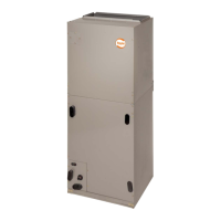
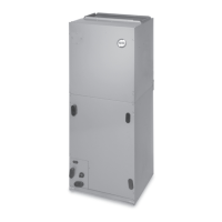
INTRODUCTION
Model PF4MNA Fan Coils are designed for flexibility and can be used
for upflow, horizontal, or downflow (kit required) and manufactured and
mobile home applications. These units are designed to meet the low air
leak requirements currently in effect. Because of this, the units need
special attention in the condensate pan and drain connection area and
when brazing tubing. These units are designed specifically for R-410A
refrigerant and must be used only with R-410A refrigerant air
conditioners and heat pumps as shipped. These units are available for
systems of 18,000 through 60,000 Btuh nominal cooling capacity.
Factory-authorized, field-installed electric heater packages are available
in sizes 5 through 30kW. See Product Data literature for available
accessory kits.
HEATER PACKAGES
Factory-approved, field-installed, UL listed heater packages are
available from your equipment supplier. See unit rating plate for a list of
factory-approved heaters. Heaters that are not factory approved could
cause damage which would not be covered under the equipment
warranty.
INSTALLATION
CHECK EQUIPMENT
Unpack unit and move to final location. Remove carton taking care not
to damage unit.
Inspect equipment for damage prior to installation. File claim with
shipping company if shipment is damaged or incomplete. Locate unit
rating plate which contains proper installation information. Check rating
plate to be sure unit matches job specifications.
MOUNT UNIT
Unit can stand or lie on floor, or hang from ceiling or wall. Allow space
for wiring, piping, and servicing unit.
IMPORTANT: When unit is installed over a finished ceiling and/or
living area, building codes may require a field-supplied secondary
condensate pan to be installed under the entire unit. Some localities may
allow as an alternative, the running of a separate, secondary condensate
line. Consult local codes for additional restrictions or precautions.
NOTE: Nuisance sweating may occur if the unit is installed in a high
humidity environment with low airflow.
UPFLOW INSTALLATION
If return air is to be ducted through a floor, set unit on floor over opening
and use 1/8 to 1/4-in (3 to 6 mm) thick fireproof resilient gasket between
duct, unit, and floor.
Side return is a field option on slope coil models. Cut opening per
dimensions. (Fig. 1) A field-supplied bottom closure is required.
DOWNFLOW INSTALLATION
In this application, field conversion of the evaporator is required using
accessory downflow kit along with an accessory base kit. Use fireproof
resilient gasket, 1/8 to 1/4-in (3 to 6 mm) thick, between duct, unit, and
floor.
PF4MNA
DIRECT EXPANSION FAN COIL
SIZES 018 TO 061
WARNING
!
ELECTRICAL OPERATION HAZARD
Failure to maintain proper clearances could result in personal injury or
death.
Before installing or servicing unit, always turn off all power to unit.
There may be more than 1 disconnect switch. Turn off accessory heater
power if applicable.
CAUTION
!
PRODUCT OR PROPERTY DAMAGE HAZARD
Failure to follow this warning caution may result in product or property
damage.
The conversion of the fan coil to downflow requires special procedures
for the condensate drains on both A-coil and Slope-coil units. The
vertical drains have an overflow hole between the primary and
secondary drain holes. This hole is plugged for all applications except
downflow, and must be used for downflow. During conversion process,
remove plastic cap covering vertical drains only and discard. Remove
plug from overflow hole and discard. At completion of downflow
installation, caulk around vertical pan fitting to door joint to retain low
air leak performance of the unit.
Question and Answer IconNeed help?

Do you have a question about the Carrier PF4MNA and is the answer not in the manual?

Overview

The PF4MNA Direct Expansion Fan Coil is a versatile indoor air handling unit designed for residential and manufactured home applications. It is compatible with R-410A refrigerant air conditioners and heat pumps, and is available for systems with nominal cooling capacities ranging from 18,000 to 60,000 Btuh. The unit is designed to meet low air leak requirements, which necessitates special attention during installation, particularly around the condensate pan and drain connections, and when brazing tubing.

Function Description:

The primary function of the PF4MNA fan coil is to circulate air, condition it (cooling or heating), and distribute it throughout a space. When connected to an outdoor air conditioner, it provides cooling. When connected to a heat pump, it provides both heating and cooling. Factory-authorized, field-installed electric heater packages, available in sizes from 5 to 30kW, can be added to provide supplemental or emergency electric heat. The unit can be configured for upflow, horizontal left, horizontal right (with conversion kit), or downflow (with conversion kit) applications, offering significant installation flexibility.

Important Technical Specifications:

  • Refrigerant Compatibility: Specifically designed for R-410A refrigerant.
  • Cooling Capacity: Available for systems from 18,000 to 60,000 Btuh.
  • Electric Heater Packages: Available in 5 to 30kW sizes.
  • Low Air Leak Design: Meets current low air leak requirements.
  • Drain Connections: Equipped with primary and secondary 3/4-inch FPT drain connections.
  • Electrical: Transformer is factory wired for 230V operation, with provisions for 208V applications. Low voltage circuit protection is provided by a 5-amp fuse (for sizes 018, 024, 030, 036, 042, 048, 060) or an inline 5-amp automotive type fuse (for sizes 019, 025, 031, 037, 043, 049, 061).
  • Airflow Performance: Detailed airflow tables (CFM) are provided for various external static pressures (in. wc) and blower speeds (High, Medium, Low), with corrections for dry-to-wet coil conditions and electric heater static pressure drop. Airflow is based on dry coil at 230V with factory-approved filter and electric heater. Airflow at 208V is approximately 10% lower for certain models (018, 024, 030, 036, 042, 048, 060), while X13 motor models (019, 025, 031, 037, 043, 049, 061) maintain similar airflow at 208V due to constant torque.
  • Clearances: Minimum 24-inch (610 mm) clearance from access panels is recommended for manufactured housing applications. For 20-30kW electric heaters, a 1-inch (25 mm) clearance to combustible materials is required for the first 36-inches (914 mm) of supply duct.

Usage Features:

  • Installation Flexibility: Can be installed in upflow, horizontal (left or right), or downflow configurations. Downflow and horizontal right applications require specific accessory kits and conversion procedures.
  • Modular Design (Sizes 060 and 061): These larger units can be disassembled for easier transport and reassembly in confined installation spaces.
  • Condensate Management: Requires proper installation of primary and secondary condensate traps to ensure optimal drainage and prevent property damage. Full-size P-traps are essential, and shallow running traps are inadequate. An external secondary condensate pan or a separate secondary condensate line may be required by local codes if the unit is installed over a finished ceiling or living area.
  • Air Duct Connections: Supply-air duct connects over 3/4-inch (19 mm) flanges. Flexible connectors are recommended to prevent vibration transmission. Heat-resistant material is required for flexible connectors at the discharge when an electric heater is installed. Ductwork in unconditioned spaces must be insulated and vapor-barriered.
  • Motor Speed Selection: For models 018, 024, 030, 036, 042, 048, 060, fan speed is selected at the printed-circuit board (SPT terminal). For models 019, 025, 031, 037, 043, 049, 061, fan speed is selected directly at the motor (taps 1, 2, or 3). Low speed (red) is for mismatched outdoor units, medium speed (blue) for straight matched operations, and high speed (black) for high external static duct systems.
  • Time Delay Relay (TDR): Models 018, 024, 030, 036, 042, 048, 060 feature a TDR jumper on the PCB, which can be severed to disable the TDR function. Some speed taps on X13 motors (019, 025, 031, 037, 043, 049, 061) are pre-programmed with a time delay circuit.
  • Heater Staging: Controls are factory-circuited for single-stage operation. Two-stage and three-stage operation require outdoor thermostat kits (KHAOT0301FST and KHAOT0201SEC).
  • Low Voltage Wiring: Uses 18 AWG color-coded, insulated wire for connections up to 100 feet (30 m); 16 AWG for longer runs. All wiring must be NEC Class 1 and separated from incoming power leads.
  • Manufactured Housing Applications: Unit must be secured to the structure using field-supplied hardware. Supplemental electric heat must be locked out at outdoor temperatures above 40°F (4°C), except for heat pump defrost cycles, as per Code of Federal Regulations, Title 24, Chapter XX, Part 3280.714.
  • Accessory Connections: Provisions for connecting electronic air cleaners (requires field-supplied transformer) and humidifiers/humidistats.

Maintenance Features:

  • Filter Access: Units should never be operated without a filter. Factory-authorized filter kits can be used for internal filter placement. For applications where internal access is impractical, a field-supplied filter must be installed in the return air duct system.
  • Periodic Maintenance: To ensure high performance and minimize equipment failure, periodic maintenance by a qualified dealer is essential. The only consumer-recommended maintenance is monthly filter replacement or cleaning.
  • Condensate Trap Priming: All condensate traps must be primed and tested for leaks after installation.
  • Insulation: Condensate traps located above a living area should be insulated.
  • Brazing Precautions: A brazing shield must be used when connecting refrigerant tubing to prevent damage to the unit surface and condensate pan fitting caps. Wet cloths should be wrapped around fittings to protect TXV and factory-made joints during brazing.

Carrier PF4MNA Specifications

General IconGeneral
BrandCarrier
ModelPF4MNA
CategoryFan
LanguageEnglish

Related product manuals