PF4MNA: Installation Instructions
Manufacturer reserves the right to change, at any time, specifications and designs without notice and without obligations.
7
GROUND CONNECTIONS
NOTE: Use UL listed conduit and conduit connectors for connecting
supply wire(s) to unit to obtain proper grounding. Grounding may also
be accomplished by using grounding lugs provided in control box.
A05182
Fig. 16 – Transformer Connections
MINIMUM CFM AND MOTOR SPEED SELECTION
Units with or without electric heaters require a minimum CFM. Refer to
the unit wiring label to ensure that the fan speed selected is not lower
than the minimum fan speed indicated. Fan speed selection for sizes 018,
024, 030, 036, 042, 048 and 060 is done at the fan relay printed-circuit
board. To change motor speeds, disconnect fan lead used on relay
terminal (SPT) and replace with motor speed tap desired. (Fig. 18) Save
insulating cap and place on motor lead removed from relay.
A09390
Fig. 17 – Transformer Connections
NOTE: In low static applications, lower motor speed tap should be used
to reduce possibility of water being blown off coil. Sizes 018 through
036 have 2 motor speed taps. Sizes 042, 048 and 060 have 3 motor speed
taps. Low speed (red) is designed for mismatched outdoor unit
applications. Medium speed (blue) is designed for straight matched
operations. High speed (black) is used with high external static duct
systems of straight matched systems.
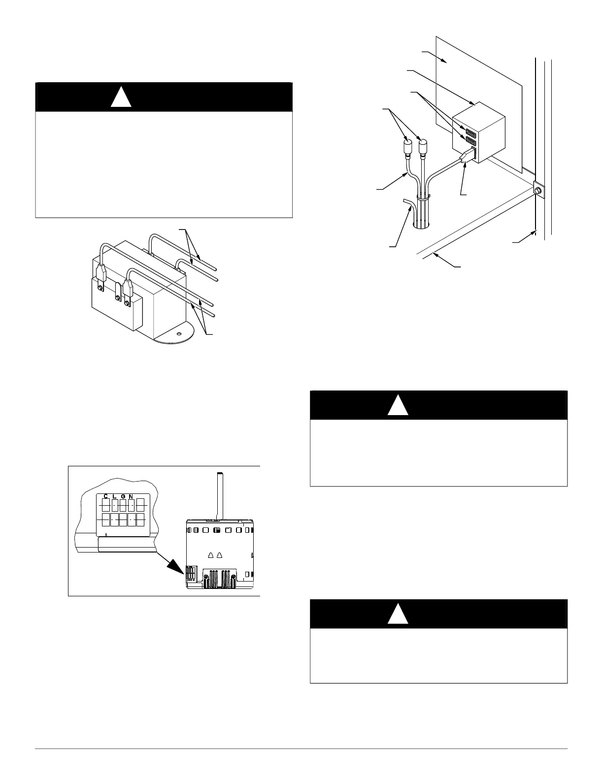
The fan speed selection on the 019, 025, 031, 037, 043, 049, and 061
models is done at the motor. (Fig. 17) To change motor speeds,
disconnect fan lead from terminal 2 and move to desired speed tap; low
speed (one), medium (two), and high (three).
A97529
Fig. 18 – Fan Coil Relay and Speed Tap Terminal for
Sizes 018, 024, 030, 036, 042, 048, 060
REFRIGERANT TUBING CONNECTION AND
EVACUATION
Use accessory tubing package or field-supplied tubing of refrigerant
grade. Suction tube must be insulated. Do not use damaged, dirty, or
contaminated tubing because it may plug refrigerant flow-control
device. ALWAYS evacuate the coil and field-supplied tubing to 500
microns before opening outdoor unit service valves.
Units have sweat suction and liquid tube connections. Make suction tube
connection first.
1. Cut tubing to correct length.
2. Insert tube into sweat connection on unit until it bottoms.
3. Braze connection using silver bearing or non-silver bearing brazing
materials. Do not use solder (materials which melt below 800°F /
427°C). Consult local code requirements.
4. Evacuate coil and tubing system to 500 microns using a deep
vacuum method.
WARNING
!
ELECTRICAL SHOCK HAZARD
Failure to establish uninterrupted or unbroken ground could result in
personal injury and/or death.
According to NEC, NFPA 70, and local codes, the cabinet must have an
uninterrupted or unbroken ground to minimize personal injury if an
electrical fault should occur. The ground may consist of electrical wire
or metal conduit when installed in accordance with existing electrical
codes. If conduit connection uses reducing washers, a separate ground
wire must be used.
230
C
208
BRN
RED
YEL
BLK
SECONDARY
PRIMARY
CAUTION
!
PRODUCT DAMAGE HAZARD
Failure to follow this caution may result in product or property damage.
A brazing shield MUST be used when tubing sets are being brazed to
the unit connections to prevent damage to the unit surface and
condensate pan fitting caps.
CAUTION
!
PRODUCT DAMAGE HAZARD
Failure to follow this caution may result in product or property damage.
Wrap a wet cloth around rear of fitting to prevent damage to TXV and
factory-made joints.
INSULATING CAP (2)
MOTOR SPEED
TAP LEADS
COMMON YELLOW
FAN DECK
WRAPPER
SPEED TAP
TERMINAL
PCB
FAN RELAY
SINGLE SPADE
 Loading...