PF4MNA: Installation Instructions
Manufacturer reserves the right to change, at any time, specifications and designs without notice and without obligations.
9
A03011
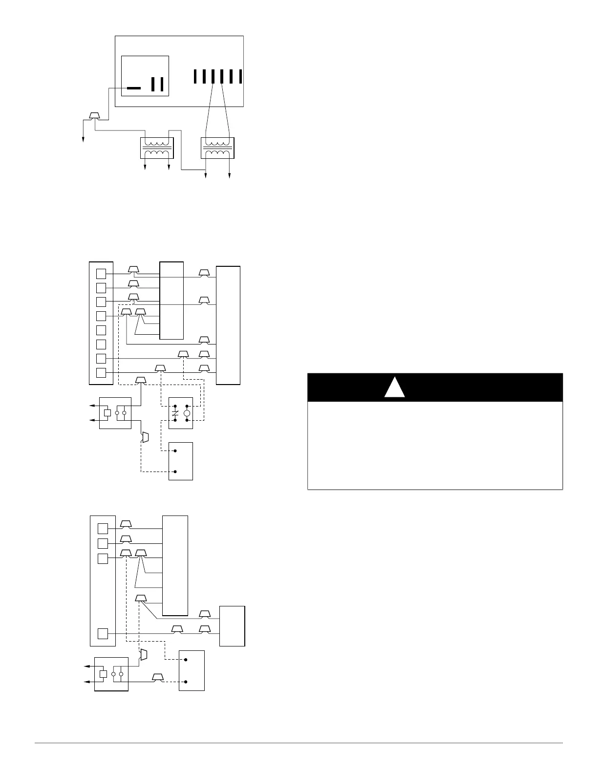
Fig. 22 – Wiring Layout of Electronic Air Cleaner
to Fan Coil
Sizes 018, 024, 030 , 036, 042, 048, & 060
A95294
Fig. 23 – Wiring Layout of Humidifier to Heat Pump
A95295
Fig. 24 – Wiring Layout of Humidifier to Fan Coil
with Electric Heat
SEQUENCE OF OPERATION
CONTINOUS FAN
Thermostat closes R to G. G energizes fan relay on PCB which
completes circuit to indoor blower motor. When G is de-energized, there
is a 90 second delay before relay opens.
COOLING MODE
Thermostat energizes R to G, R to Y, and R to O (heat pump only). G
energizes fan relay on PCB which completes circuit to indoor blower
motor. When G is de-energized, there is a 90 second delay before fan
relay opens.
HEAT PUMP HEATING MODE
Thermostat energizes R to G and R to Y. G energizes fan relay on PCB
which completes circuit to indoor blower motor. When G is
de-energized, there is a 90-sec delay before fan relay opens.
HEAT PUMP HEATING WITH AUXILIARY
ELECTRIC HEAT
Thermostat energizes R to G, R to Y, and R to W. G energizes fan relay
on PCB which completes circuit to indoor blower motor. W energizes
electric heat relay(s) which completes circuit to heater element(s). When
W is de-energized, electric heat relay(s) open, turning off heater
elements. When G is de-energized there is a 90 second delay before fan
relay opens.
ELECTRIC HEAT OR EMERGENCY HEAT MODE
Thermostat closes R to W. W energizes electric heat relay(s) which
completes circuit to heater element(s). Blower motor is energized
through normally closed contacts on fan relay. When W is de-energized,
electric heat relay(s) opens.
START-UP PROCEDURES
Refer to outdoor unit Installation Instructions for system start-up
instructions and refrigerant charging method details.
CARE AND MAINTENANCE
To continue high performance and minimize possible equipment failure,
it is essential that periodic maintenance be performed on this equipment.
Consult your local dealer as to the proper frequency of maintenance
contract.
The ability to properly perform maintenance on this equipment requires
certain mechanical skills and tools. If you do not possess these, contact
your dealer for maintenance. The only consumer service recommended
or required is filter replacement or cleaning on a monthly basis.
RFAN RELAY
NO
230VAC
COM
NC
NONCSPT
WIRE
NUT
TO
BLOWER
MOTOR
CONVERSION KIT
TRANSFORMER
FROM MOLEX
PLUG AND
TRANSFORMER
(IN UNIT)
TO EAC
208/230VAC COM
24VAC
COM 208/
230
COM
CONTROL BOARD
GTC
C C
R
G
C
E
L
O
Y
THERMOSTAT
R
R
C
O
Y
G
C
W
2
W
2
W
2
W
3
E
FAN COIL
(CONTROL)
HEAT PUMP
(CONTROL)
RED
GRY
BRN
WHT
WHT
BLU
VIO
HUMIDISTAT
RELAY
FAN HUMIDIFIER
115V
M
R
G
W
Y
THERMOSTAT
R
G
W
2
W
3
E
C
FAN COIL
(CONTROL)
C
Y
AIR COND.
HUMIDISTAT
FAN HUMIDIFIER
115V
RED
GRY
WHT
WHT
BLU
VIO
BRN
M
CAUTION
!
PRODUCT DAMAGE HAZARD
Failure to follow this caution may result in poor unit performance
and/or product damage.
Never operate unit without a filter. Factory authorized filter kits may be
used when locating the filter inside the unit. For those applications
where access to an internal filter is impractical, a field-supplied filter
must be installed in the return air duct system.