PF4MNA: Installation Instructions
Manufacturer reserves the right to change, at any time, specifications and designs without notice and without obligations.
6
HEATER STAGING
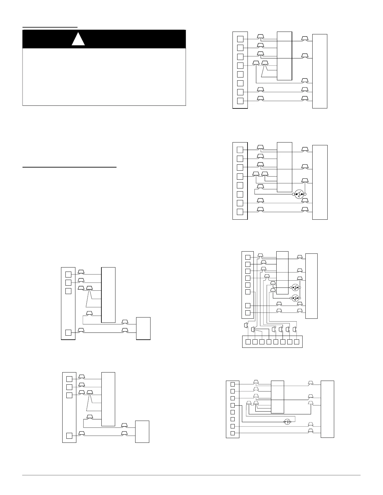
The controls are factory circuited for single-stage operation. For 2-stage
operation, use outdoor thermostat kit Part No. KHAOT0301FST, and for
3-stage use both kits Part No. KHAOT0201SEC and KHAOT0301FST.
When 2 stages are desired, cut W3 at the W2 wire nut, strip and
reconnect per the thermostat kit instruction. (Fig. 13)
When 3 stages are desired, cut the W2 wire nut off and discard. Strip
W2, W3, and E and reconnect per thermostat kit instructions (Fig. 14).
TRANSFORMER INFORMATION
Transformer is factory wired for 230V operation. For 208V applications,
disconnect the black wire from the 230V terminal on transformer and
connect it to the 208V terminal (Fig. 16).
NOTE: When 3 stages are used or any time the E terminal is not tied to
W2, the emergency heat relay, part of outdoor kit Part No.
KHAOT0201SEC, must be used.
MANUFACTURED HOUSING
In manufactured housing applications, the Code of Federal Regulations,
Title 24, Chapter XX, Part 3280.714 requires that supplemental electric
heat be locked out at outdoor temperatures above 40°F (4°C), except for
a heat pump defrost cycle. Refer to Fig. 15 for typical low voltage wiring
with outdoor thermostat.
A94058
Fig. 10 – Wiring Layout Air Conditioning Unit
(Cooling Only)
A94059
Fig. 11 – Wiring Layout Air Conditioning Unit
(Cooling and 1-Stage Heat)
A94060
Fig. 12 – Wiring Layout Heat Pump Unit
(Cooling and 2-Stage Heat with No Outdoor Thermostat)
A94061
Fig. 13 – Wiring Layout Heat Pump Unit
(Cooling and 2-Stage Heat with 1 Outdoor Thermostat)
A94062
Fig. 14 – Wiring Layout Heat Pump Unit
(Cooling and 2-Stage Heat with 2 Outdoor Thermostats)
A03088
Fig. 15 – Wiring Layout Heat Pump Unit
(Cooling and 2-Stage Heat for Manufactured Housing)
CAUTION
!
PROPERTY DAMAGE HAZARD
Failure to follow this caution may result in product or property damage.
If W2, W3, and E on any 3 stage heater (18, 20, 24, or 30kW), are
individually connected as with outdoor thermostats or any other
situation, emergency heat relay must be used. This relay is in kit Part
No. KHAOT0201SEC and is normally used with kit Part No.
KHAOT0301FST for 2 outdoor thermostat system.
R
G
W
Y
THERMOSTAT
RED
GRY
WHT
BLU
VIO
BRN
WHT
R
G
W
2
W
3
E
C
FAN COIL
(CONTROL)
C
Y
AIR COND.
R
G
W
Y
THERMOSTAT
R
G
W
2
W
3
E
C
FAN COIL
(CONTROL)
C
Y
AIR COND.
RED
GRY
WHT
WHT
BLU
VIO
BRN
R
G
C
E
L
O
Y
THERMOSTAT
R
R
C
O
Y
G
C
W
2
W
2
W
2
W
3
E
FAN COIL
(CONTROL)
HEAT PUMP
(CONTROL)
A94060
RED
GRY
BRN
WHT
BLU
VIO
R
G
C
E
L
O
Y
THERMOSTAT
R
R
C
O
Y
G
C
W
2
W
2
W
2
W
3
E
ODTS
FAN COIL
(CONTROL)
HEAT PUMP
(CONTROL)
RED
GRY
BRN
WHT
VIO
BLU
R
G
C
L
E
O
C147C96 3
Y
THERMOSTAT
R
R
C
O
Y
G
C
W
2
W
2
W
2
W
3
E
FAN COIL
(CONTROL)
EMERGENCY HEAT RELAY
HEAT PUMP
(CONTROL)
ODTS1
ODTS2
RED
GRY
BRN
WHT
BLU
VIO
R
E
W2
R
C
THERMOSTAT
FAN COIL
(CONTROL)
HEAT PUMP
(CONTROL)
G
C
W2
E
L
G
C
R
O
Y
ODTS
O
Y
W3
W2


 To Next Page