PG92MSA: Installation, Start-up, Operating and Service and Maintenance Instructions
Manufacturer reserves the right to change, at any time, specifications and designs without notice and without obligations.
25
A190079
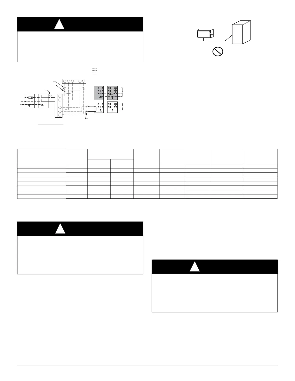
Fig. 33 – Typical Single-Stage Wiring Diagram
A190279
Fig. 34 – Field-Supplied External Electrical Box on Furnace Casing
Table 11 – Electrical Data
115-V Wiring
Furnace must have a 115-V power supply properly connected and
grounded.
NOTE: Proper polarity must be maintained for 115-V wiring. If polarity
is incorrect, control LED status indicator light will flash rapidly and
Status code (10.1) is displayed. The furnace will NOT operate.
Verify that the voltage, frequency, and phase correspond to that specified
on unit rating plate. Also, check to be sure that service provided by
utility is sufficient to handle load imposed by this equipment. Refer to
rating plate or Table for equipment electrical specifications.
U.S.A. Installations: Make all electrical connections in accordance with
the current edition of the National Electrical Code (NEC) NFPA 70 and
any local codes or ordinances that might apply.
Canada Installations: Make all electrical connections in accordance
with the current edition of the Canadian Electrical Code CSA C22.1 and
any local codes or ordinances that might apply.
Use a separate, fused branch electrical circuit with a properly sized fuse
or circuit breaker for this furnace. See Table for wire size and fuse
specifications. A readily accessible means of electrical disconnect must
be located within sight of the furnace.
WARNING
!
FIRE HAZARD
Failure to follow this warning could result in personal injury, death, or
property damage.
Do not connect aluminum wire between disconnect switch and furnace.
Use only copper wire. See Fig. 34.
115-V FIELD-
SUPPLIED
DISCONNECT
AUXILIARY
J-BOX
24-V
TERMINAL
BLOCK
THREE-WIRE
HEATING-ONLY
FIVE WIRE
NOTE 1
NOTE 2
FIELD-SUPPLIED
DISCONNECT
CONDENSING
UNIT
TWO
WIRE
FURNACE
C
O
N
T
R
O
L
R
G
COM
WCR GY
GND
GND
FIELD 24-V WIRING
FIELD 115-, 208/230-, 460-V WIRING
FACTORY 24-V WIRING
FACTORY 115-V WIRING
208/230- OR
460-V
THREE
PHASE
208/230-V
SINGLE
PHASE
BLOWER DOOR SWITCH
WHT
BLK
WHT
BLK
NOTES:
Connect Y-terminal in furnace as shown for proper blower operation.
Some thermostats require a "C" terminal connection as shown.
If any of the original wire, as supplied, must be replaced, use
m
r
iv
l
n
wir
.
W
Y
GND
THERMOSTAT
TERMINALS
1.
2.
3.
COPPER
WIRE ONLY
ELECTRIC
DISCONNECT
SWITCH
ALUMINUM
WIRE
FURNACE SIZE
VOLTS-
HERTZ-
PHASE
OPERATING VOLTAGE
RANGE
*
*. Permissible limits of the voltage range at which the unit operates satisfactorily.
MAXIMUM
UNIT
AMPS
UNIT
AMPACITY
†
†. Unit ampacity = 125 percent of largest operating component’s full load amps plus 100 percent of all other potential operating components’ (EAC, humidifier, etc.) full load
amps
MINIMUM
WIRE SIZE
AWG
MAXIMUM
WIRE LENGTH
FT (M)
‡
‡. Time-delay type is recommended.
MAXIMUM
FUSE OR CKT
BKR AMPS
**
**. Length shown is as measured one way along wire path between furnace and service panel for maximum 2 percent voltage drop.
Maximum Minimum
36040A 115-60-1 127 104 7.4 10.2 14 36 (11.1) 15
36040B 115-60-1 127 104 7.4 10.2 14 36 (11.1) 15
36060A 115-60-1 127 104 7.5 10.3 14 36 (11.0) 15
42060B 115-60-1 127 104 7.5 10.3 14 36 (11.0) 15
48080B 115-60-1 127 104 11.0 14.7 14 25 (7.7) 15
60080C 115-60-1 127 104 11.0 14.7 14 25 (7.7) 15
60100C 115-60-1 127 104 11.1 14.8 14 25 (7.6) 15
60120D 115-60-1 127 104 11.1 14.8 14 25 (7.6) 15
CAUTION
!
FURNACE MAY NOT OPERATE HAZARD
Failure to follow this caution may result in intermittent furnace
operation.
Furnace control must be grounded for proper operation or else control
will lock out. Control must remain grounded through green/yellow wire
routed to gas valve and manifold bracket screw.