There should not be any heat source or stream
near the unit.
There should not be any obstacles blocking the
air circulation.
A place where air circulation in the room is good.
A palce where drainage can be easily done.
A palce where noise prevention is taken into
consideration.
Do not install the unit near the door way.
Ensure the spaces indicated by arrows from the
wall,ceiling,fence or other obstacles.
There should not be any direct sunlight. If unavoidable,
sunlight prevention should be taken into consideration.
1. Fit the installation plate horizontally
on structural parts of the wall with
spaces around the installation plate.
2. If the wall is made of brick, concrete
or the like, drill eight (8) 5mm diameter
holes in the wall.Insert Clip anchor for
appropriate mounting screws.
3. Fit the installation plate on the wall
with eight (8) type A screws.
Fit the Installation Plate and drill
holes in the wall according to the
wall structure and corresponding
mounting points on the installation
plate. The installation plate
provided with the machine differ
from appliance to appliance.
(Dimensions are in mm unless
otherwise stated)
Correct orientation
of Installation Plate
1. Determine hole positions according to left and right
side of the installation plate. The hole center is obtained
by measuring the distance as shown in the diagram above.
2. Dirll the piping plate hole with φ65mm hole-core drill.
3. Drill the piping hole at either the right or the left and the
hole should be slightly slanted to the outdoor side.
4. Always use wall hole conduit when drilling metal grid,
metal plate or the like.
1. For the left-hand and right-hand piping,
remove the pipe cover from the side panel.
2. For the rear-right-hand and rear-left-hand
piping, install the piping as shown.
3. Bundle the tubing, connecting cable, and
drain hose with tape securely, evenly as
shown in Figure on the right.
Because the condensed water from rear
of the indoor unit is gathered in ponding
box and is piped out of room. Do not put
anything else in the box.
1. Run the drain hose sloping downward.
Do not install the drain hose as illustrated
in Figures.
2. When connecting extension drain hose,
insulate the connecting part of extension
drain hose with a shield pipe, do not let
the drain hose slack.
Connect the indoor unit first, then the
outdoor unit.
Do not allow the piping to let out from the
back of the indoor unit.
Be careful not to let the drain hose slack.
Heat insulated both of the auxiliary piping.
Be sure that the drain hose is located at
the lowest side of the bundle. Locating at
the upper side can cause drain pan to
overflow inside the unit.
Never intercross nor intertwist the power
wire with any other wiring.
Run the drain hose slopped downward to
drain out the condensed water smoothly.
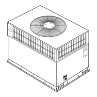
Anchor the outdoor unit with a bolt and nut φ10 or
φ8 tightly and horizontally on a concrete or rigid mount.
O
ut
d
oor
u
ni
t
d
ime
n
s
i
o
n
m
m
(L1
x
H
x
W1)
L2(mm) W2(mm)
530
290
560
549
481
335
276
276
Mounting dimensions
760x590x285
845x700x320
780x540x250
670x540x265
1. Pass the piping through the hole in the wall.
2. Hook the indoor unit onto the upper portion
of installation plate(Engage the indoor unit with
the upper edge of the installation plate). Ensure
the hooks are properly seated on the installation
plate by moving it in left and left.
3. Piping can easily be made by lifting the indoor
unit with a cushioning material between the
indoor unit and the wall. Get it out after finish
piping.
4. Press the lower left and right side of the unit
against the installation plate until hooks
engages with the their slots.
INSTALLATION MANUAL FOR ROOM
AIR CONDITIONER
(Split Wall-Mounted Type)
SELECT THE BEST LOCATION
Indoor unit
DRILL A HOLE IN THE WALL
Outdoor unit
Settlement of outdoor unit
FIT THE INSTALLATION PLATE
2
CONNECTIVE PIPE AND DRAINAGE INSTALLATION
3
NOTE:
NOTE:
Fit the Installation Plate
Connective pipe installation
Draina ge
CAUTION
Indoor unit installation
1
The mounting wall is strong and solid
enough to prevent it from the vibration.
" "
"
"
If an awning is built over the unit to prevent
direct sunsight or rain,be careful that heat
radiation from the condenser is not obstructed.
There should not be any animal or plant which
could be affected by hot air discharged.
Keep the spaces indicated by arrow from wall
ceiling, fence or other obstacles.
Do not place any obstacles which may cause
a short circuit of the discharged air.
I
N
D
O
O
R
U
N
I
T
150mm or more to ceiling
Indoor unit outline
Installation plate
292
Right rear side
refrigerant
pipe hole φ65
Left rear side
refrigerant
pipe hole φ65
120mm or
more to wall
120mm or
more to wall
920
45
185
150
45
A
45
B
Right rear side
refrigerant
pipe hole φ65
Installation plate
Indoor unit outline
Left rear side
refrigerant
pipe hole φ65
150mm or more to ceiling
120mm or
more to wall
120mm or
more to wall
Model A (A: 710, B: 250, C:100, D: 160)
Model B( )A: 790, B:265, C:100, D: 150
Model C
Model D
45
C
D
The seriousness is classified by the following indications.
This symbol indicates the possibility of death or serious injury.
This symbol indicates the possibility of injury or damage to property.
1) This equipment must be earthed and installed with earth leakage current breaker. It may cause
electrical shock if grounding is not perfect.
2) Do not install the unit at place where leakage of flammable gas may occur. In case gas leaks and
accumulates at surrounding of the unit, it may cause fire.
3) Carry out drainage piping as mentioned in installation instructions. If drainage is not perfect, water
may enter the room and damage the furniture.
1) Install according to this installation instructions strictly. If installation is defective, it will cause water
leakage, electrical shock fire.
2) Use the attached accessories parts and specified parts for installation, otherwise, it will cause the set
to fall, water leakage, electrical shock fire.
3) Install at a strong and firm location which is able to withstand the set s weight. If the strength is not
enough or installation is not properly done, the set will drop and cause injury.
4) For electrical work, follow the local national wiring standard, regulation and this installation instructions.
An independent circuit and single outlet must be used. If electrical circuit capacity is not enough or
defect found in electrical work, it will cause electrical shock fire.
5) Use the specified cable and connect tightly and clamp the cable so that no external force will be acted
on the terminal. If connection or fixing is not perfect, it will cause heat-up or fire at the connection.
6) Wiring routing must be properly arranged so that control board cover is fixed properly. If control board
cover is not fixed perfectly, it will cause heat-up at connection point of terminal, fire or electrical shock.
7) When carrying out piping connection, take care not to let air substances other than the specified
refrigerant go into refrigeration cycle. Otherwise, it will cause lower capacity, abnormal high pressure
in the refrigeration cycle, explosion and injury.
8) Do not modify the length of the power supply cord or use of extension cord, and do not share the
single outlet with other electrical appliances. Otherwise, it will cause fire or electrical shock.
SAFETY PRECAUTIONS
CAUTION
WARNING
CAUTION
WARNING
Please read this installation manual completely before installing the product.
If the power cord is damaged, replacement work shall be performed by authorised personnel only.
Installation work must be performed in accordance with the national wiring Standards by authorised
personnel only.
Contact an authorised service technician for repair, maintenance or installation of this unit.
This appliance is not intended for use by persons(including children) with reduced physical, sensory
or mental capabilities, or lack of experience and knowledge, unless they have been given supervision
or instruction concerning use of the appliance by a person responsible for their safety.
Children should be supervised to ensure that they do not play with the appliance.
The design and specifications are subject to change without prior notice for product improvement.
Consult with the sales agency or manufacturer for details.
All the pictures in the instructions are for explanation purposes only. The actual shape should prevail.
1
2
3
4
5
7
8
9
6
Installation Plate
Clip Anchor
Self-tapping Screw A ST3.9x25
Seal(For cooling & heating models only)
Drain Joint(For cooling & heating models only)
Connec ti ng
pipe
Assemb ly
Liquid s id e
Gas side
Remote controller
Self-tapping Screw B ST2.9x10
Φ6.35
Φ9.52
Φ9.52
Φ12.7
Φ 16
Parts you must purchase. The pipe
size differ from appliance to appliance.
Consult the technician for the proper
size.
1
5-8(de pe nd ing on models )
5-8(de pe nd ing on models )
1
1
1
2
1
Except the above parts provided,the other parts needed during installation you must
purchase.
Remote controller holder
ACCESSORIES
Number
Name of Accessories
Qty
NOTE:
option al
parts
120mm or more
from the wall
120mm or more
from the wall
45
150mm or more from the ceiling
Indoor Unit Outline
70
Hooked Part
110
1080
330
65
65
4
5
2020001B3679
STELLAR INVERTER SERIES