4
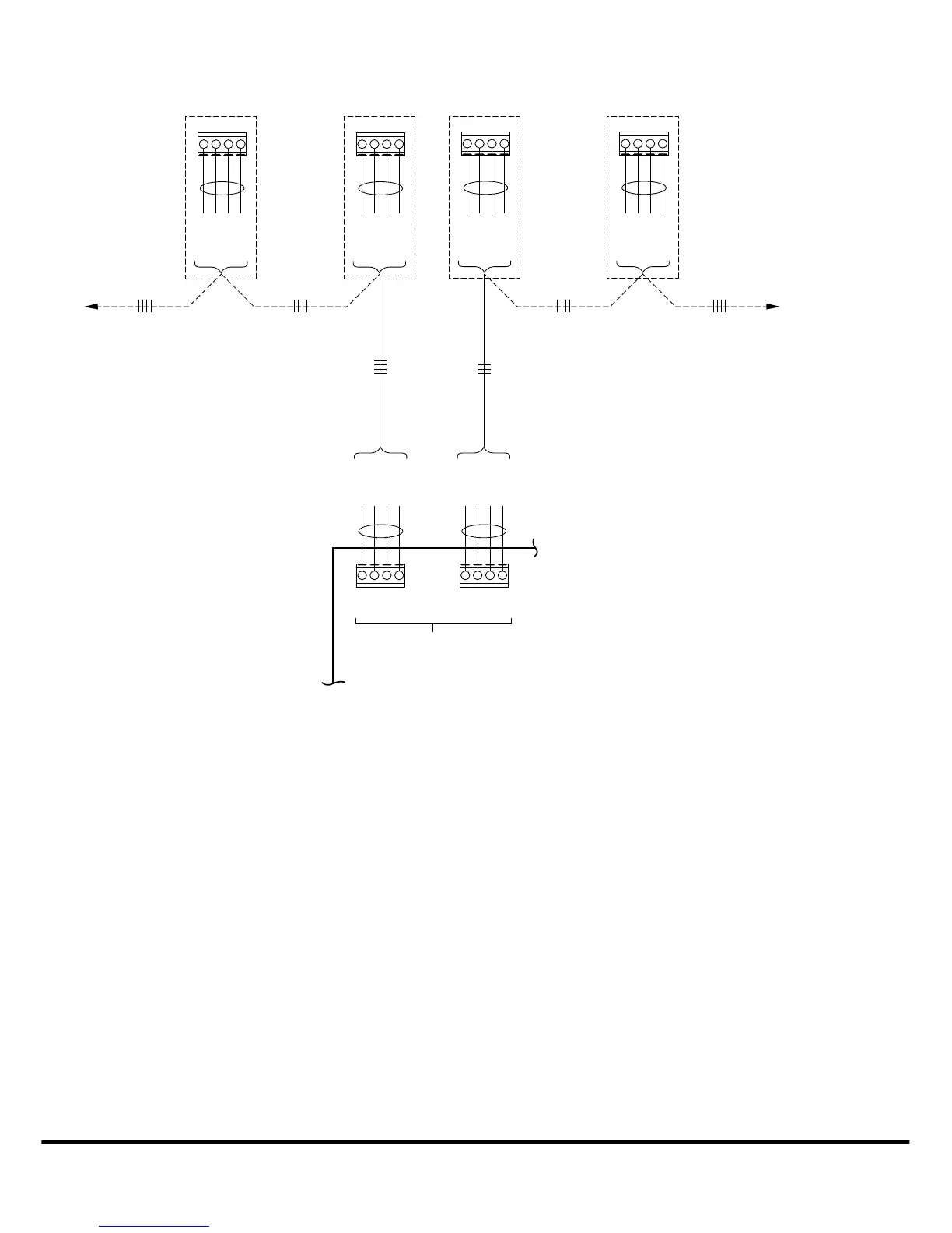
* ABCD Connections are in Parallel with each other.
Smart Sensors and Equipment may be connected in any combination.
For easier troubleshooting, the installer may elect to use one terminal block
for wall control and smart sensor connections, and the other for equipment connections.
NOTE:
DAMPER CONTROL MODULE
ZONES 1-4
ABCD
RED
GREEN
YELLOW
WHITE
SMART SENSOR(S)
TO WALL CONTROL, AND/OR
DAISY CHAIN
OPTION
TO OTHER
SMART SENSORS
IF AVAILABLE
TO EQUIPMENT OR
ACCESSORY CONNECTIONS
A
B
C
D
RED
COMMUNICATION
BUS
*
GREEN
YELLOW
WHITE
A
B
C
D
RED
GREEN
YELLOW
WHITE
ABCD
RED
GREEN
YELLOW
WHITE
ABCD
RED
GREEN
YELLOW
WHITE
ABCD
RED
GREEN
YELLOW
WHITE
TO EQUIPMENT, AND/OR
DAMPER CONTROL MODULE
(ZONES 5-8)
A04135
Fig. 3 -- Typical Smart Sensor Wiring diagram
Copyright 2012 Carrier Corp. S 7310 W. Morris St. S Indianapolis, IN 46231 Edition Date: 10/12
Manufacturer reserves the right to change, at any time, specifications and designs without notice and without obligations.
C a t a l o g N o : Z O N E S M S --- 0 2 S I
R e p l a c e s : Z O N E S M S --- 1 S I

 Loading...


