Do you have a question about the Carrier SmartVu and is the answer not in the manual?
Provides essential guidelines for safe installation, start-up, and servicing of the equipment.
Details crucial precautions for working with electrical components and handling equipment safely.
Describes the SmartVuTM control's role as a user interface and configuration tool for heat pumps.
Outlines the system's capabilities in managing compressors, pumps, and user interface operations.
Lists the key components managed by the controller for effective unit operation.
Explains the three independent operating modes: Local, Remote, and Network.
Details the main controller and associated boards managing unit operations and information.
Explains the 24 VAC power supply to the control boards and restart behavior.
Describes the function of LEDs on boards for indicating operation status and potential failures.
Details the physical connections for communication protocols like LEN, CCN, Modbus, and BACnet.
Explains the types and functions of pressure transducers used for monitoring circuit pressures.
Lists and describes various temperature sensors critical for system monitoring and control.
Describes actuators like EXV, four-way valve, and flow switches that control unit functions.
Summarizes terminal block connections for various inputs and outputs, detailing their functions.
Provides guidance on proper RS485 wiring schemes and daisy chain configuration for reliable communication.
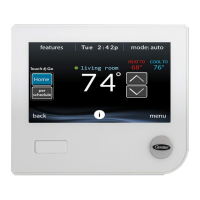
Introduces the 4.3-inch color touch screen for alarms, status, and web connectivity.
Describes the home screen as the starting point, showing basic unit operation information.
Explains the circuit view accessible via a web browser for detailed component status.
Details the information displayed in the status bar for user feedback on actions and errors.
Explains the function of the main navigation buttons located in the header.
Describes the subheader buttons used for navigating within specific views, like Circuit View.
Lists and describes various other buttons for saving, canceling, logging in/out, and confirming actions.
Guides users through calibrating the touch screen for accurate software response.
Explains warning messages used to inform users about problems and failed actions.
Details the process and messages related to saving or discarding parameter modifications.
Provides access to main control parameters, inputs, and outputs via icons.
Allows modification of user-configurable parameters like pump settings, schedules, and networks.
Enables setting up time schedules for unit on/off times, setpoints, and hot water.
Allows users to define up to 16 holiday periods for customized operation.
Configures network settings for BACnet/Modbus and defines email accounts for notifications.
Allows verification of software, hardware, network info, and display settings like language.
Provides access to different user levels (User, Service, Factory) for system configuration.
Enables selecting operating modes (Local On/Off, Schedule, Remote, Network, Master) to start or stop the unit.
Allows users to monitor current and historical alarms, and reset alarms requiring manual intervention.
Explains how unit state is determined by factors like operating type, overrides, and alarms.
Details how the control adjusts compressor numbers to maintain heat exchanger setpoints.
Describes the function to limit unit power consumption, often via external contacts or network settings.
Explains control of internal or external pumps, including constant and variable speed logic.
Defines the control point as the target water temperature, adjusted by setpoint and reset calculations.
Covers optimization of heating and domestic hot water (DHW) production using a three-way valve.
Details options for boiler activation and electric heater stages as supplemental heating.
Explains how the control manages defrost cycles to prevent frost buildup on the outdoor coil.
Describes how two units can be linked for master/slave control, managed by a single master unit.
Explains BACnet/IP communication for integration with building management systems.
Explains Modbus communication for integration with building management systems.
Details the requirement for activation keys to enable additional software options like BACnet/Modbus.
Guides on setting up time schedules for unit operation modes and setpoints.
Allows definition of up to 16 holiday periods to customize unit operation during specific dates.
Enables visualization of unit operations and monitoring of selected parameters via graphs.
Describes how to access and control unit parameters remotely via a web browser.
Explains how to access technical documents related to the unit via the SmartVuTM control interface.
Details fault tracing functions protecting the unit and monitoring operating conditions.
Explains how to view a list of up to 10 currently active alarms on the unit.
Describes configuring recipients for email notifications upon new alarms or resets.
Guides on manually resetting alarms via the touch panel or web interface.
Explains how to access the history of resolved alarms, divided into general and major alarms.
Lists various alarm codes, their possible causes, actions taken, and reset procedures.
| Brand | Carrier |
|---|---|
| Model | SmartVu |
| Category | Control Systems |
| Language | English |
