9
3.7 - Actuators
■ Electronic Expansion Valve
The electronic expansion valve (EXV) is used to adjust the
refrigerant ow. The high degree of accuracy with which the
piston is positioned provides precise control of the refrigerant
ow and suction superheat.
■ Four-way valve
This valve is used for switching the unit into the defrost mode
when necessary (see section 6.8).
■ Flow switch
For units without internal pumps, a ow switch is mounted to
ensure that the minimum ow rate required for the correct
operation and protection of the system is maintained. If the
ow switch fails, the alarm condition shuts o the unit.
■ Water pump (optional)
The controller can regulate one external water heat exchanger
pump. See section 6.4.
■ Boiler (optional)
The boiler is activated when the operating conditions are not
suitable for thermodynamic heating or the unit is down due to
a detected failure. If there is a unit fault in the heating mode
this output authorises start-up and shutdown of a boiler.
■ Electric heaters
Electric heaters are normally used as a supplementary heating
source in the heating mode.
3.8 - Terminal block connections
Connections available at the user terminal block may vary
depending on the selected options. The following table summarizes
connections at the user terminal block.
IMPORTANT: Some contacts can be accessed only when the
unit operates in Remote mode.
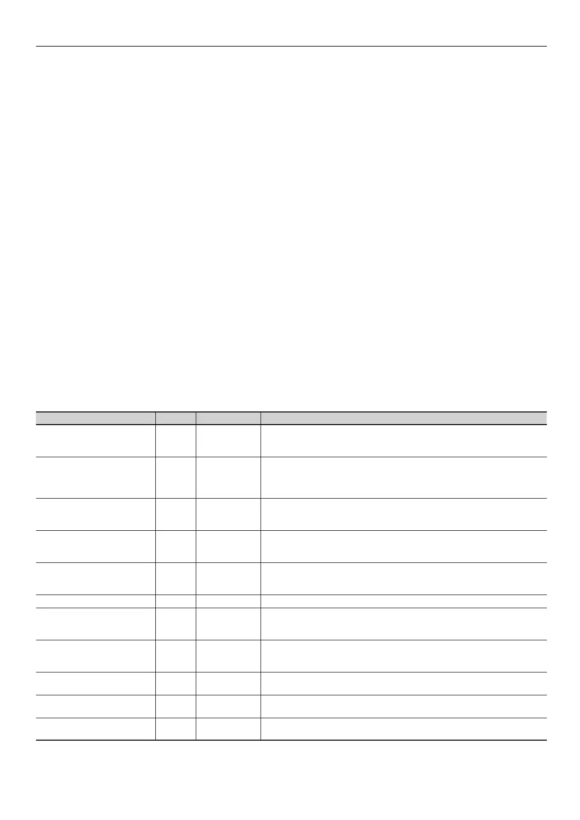
Description Board Connector Remarks
On/O Switch SIOB DI-01, 32-33
Used for the unit on/o control (Remote mode only):
open = unit is O
closed = heating allowed
Setpoint Switch SIOB DI-02, 65-66
When the unit is under remote control, the volt-free contact is used to determine
the active setpoint (see section 6.5.1):
open = heating setpoint 1 is used
closed = heating setpoint 2 is used
Limit Switch SIOB DI-03, 73-74
Used to control demand limit:
open = 100% capacity can be used, no demand limitation is applied
closed = demand limitation applied (see section 6.3)
Flow Switch / Interlock Switch SIOB DI-05, 34-35
Used to control the pump and unit operation:
open = pump continues to run
closed = pump is stopped (unit is not allowed to start)
DHW Tank Request Switch SIOB DI-06, 63-64
Used to command the domestic hot water loop in case of DHW option:
open = DHW disabled
closed = DHW allowed
Running Relay SIOB DO-05, 37-38 Used to signal a running status (at least one compressor start)
Alarm Relay SIOB DO-06, 30-31
Used to signal an alarm:
open = inactive (no alarms active)
closed = alarm(s) active
Electrical Heat Stage #1 or
Boiler
AUX1 DO-01, 51-52
Used to control the electrical heater stage 1 or boiler:
open = electrical heater or boiler not active
closed = electrical heater or boiler active
Electrical Heat Stage #2 AUX1 DO-02, 53-54
Used to control the electrical heater stage 2:
open = output inactive, closed = output active
Electrical Heat Stage #3 AUX1 DO-03, 55-56
Used to control the electrical heater stage 3:
open = output inactive, closed = output active
Electrical Heat Stage #4 AUX1 DO-04, 57-58
Used to control the electrical heater stage 4:
open = output inactive, closed = output active
NOTE: Please refer to the electrical scheme for more
information about electrical terminal identication.
3 - HARDWARE DESCRIPTION