Do you have a question about the Carrier SmartVu control and is the answer not in the manual?
Provides an overview of potential hazards and necessary precautions during installation and servicing.
Details safety measures and precautions to prevent electrical hazards during operation and maintenance.
Provides an overview of the chiller's control system functionality and architecture.
Lists and defines common abbreviations used throughout the document for clarity.
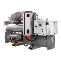
Provides a general overview of the chiller's control system components.
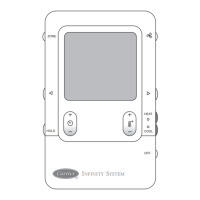
Describes the primary control unit, including its interface and key components.
Explains the function and specifications of the Integrated Starter Module for motor control.
Details the Input/Output Board, its function, and power supply.
Describes various sensors used to monitor chiller parameters, including pressure and temperature transducers.
Details the outputs controlled by the system, such as pumps, vanes, and valves.
Specifies the types of refrigerants supported by different chiller models.
Outlines the connections available at the user's terminal block on the Input/Output Board.
Details the field terminal block connections for accessing optional features and interfaces.
Specifies electrical characteristics and recommended types for communication cables.
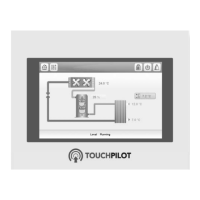
Provides an overview of the chiller's touch screen user interface features.
Describes common features of the user interface, including buttons and screen types.
Presents the main system overview screen, showing key operational parameters and status.
Allows users to configure the display language and units of measurement for the interface.
Details the user and service login procedures for accessing system functions.
Explains how to initiate or terminate the chiller's operation through the user interface.
Provides access to view and manage active alarms and warnings on the system.
Navigates to the main menu to access various system functions and settings.
Allows adjustment and viewing of operational setpoints for chiller control.
Enables users to configure various operational parameters and system settings.
Manages the chiller's operating schedule based on time and day settings.
Displays graphical trends of key operational parameters over time for analysis.
Provides status information for components of the 19XR6/7/F chiller series.
Shows a high-level overview of the chiller's current operating status and key parameters.
Displays detailed operational status and parameters related to the condenser section.
Shows detailed operational status and parameters related to the evaporator section.
Provides status information for the chiller's compressor, including operating hours and starts.
Details operational parameters of the chiller's motor, such as voltage, current, and temperature.
Displays status information for the economizer system, including pressure readings.
Shows status related to the chiller's transmission system and related components.
Details the status of the envelope control system, including valve positions and surge regions.
Provides operational status and fault information for the Variable Frequency Drive.
Outlines the steps and checks performed during the chiller's startup process.
Presents status information for the 19XR2-5/C/D/E/V chiller series.
Shows a high-level overview of the chiller's current operating status and key parameters.
Displays detailed operational status and parameters related to the condenser section.
Shows detailed operational status and parameters related to the evaporator section.
Provides status for single-stage compressor operation, including target and actual positions.
Details status for dual-stage compressor operation, including target and actual positions.
Details operational parameters of the chiller's motor, such as voltage, current, and temperature.
Shows status related to the chiller's transmission system and related components.
Details the status of the envelope control system, including valve positions and surge regions.
Provides operational status and fault information for the Variable Frequency Drive.
Outlines the steps and checks performed during the chiller's startup process.
Presents status information for the 19DV chiller series.
Shows a high-level overview of the chiller's current operating status and key parameters.
Displays detailed operational status and parameters related to the condenser section.
Shows detailed operational status and parameters related to the evaporator section.
Provides status information for the chiller's compressor, including operating hours and starts.
Details operational parameters of the chiller's motor, such as voltage, current, and temperature.
Details the status of the envelope control system, including valve positions and surge regions.
Provides operational status and fault information for the Variable Frequency Drive.
Outlines the steps and checks performed during the chiller's startup process.
Displays status information related to the chiller's purge system operations.
Defines the chiller's start and stop commands and available control modes.
Displays the current operational status of the compressor and system.
Details the sequence of pre-start tests and checks before chiller startup.
Verifies pre-start alerts and safety conditions are within acceptable limits.
Describes the steps involved in the successful startup of the chiller unit.
Outlines conditions and procedures for initiating a chiller shutdown.
Details the operation and parameters of the oil lubrication system for chillers.
Explains the use of refrigerant for compressor bearing lubrication and cooling.
Defines the target temperature maintained by the chiller's capacity control system.
Allows configuration of the primary target temperature for chiller operation.
Explains available chilled water or brine reset types for temperature control.
Describes how chiller capacity is managed by modulating guide vanes and VFD speed.
Manages the rate of compressor loading to prevent electrical demand spikes.
Details algorithms for surge prevention and protection to maintain compressor stability.
Manages EC valve operation for surge correction and low load conditions.
Maintains pressure difference between evaporator and economizer using a damper valve.
Controls a vapor source damper for pressure difference adjustment in specific chiller units.
Provides a feature to limit average load current or motor kilowatts via capacity control.
Explains how overrides prevent safety shutdowns by adjusting chiller capacity.
Manages chiller cycling off and waiting for increased load in lightly loaded conditions.
Details run time clocks for compressor, service, and start counts.
Covers control of chilled and condenser water pumps for freeze prevention.
Enables testing of controlled outputs, excluding compressor output.
Lists discrete outputs that can be forced ON or OFF during quick test mode.
Details analog outputs that can be driven to commanded positions during quick test.
Describes the procedure for calibrating guide vane position before chiller startup.
Allows rapid chiller restart to meet building load requirements, reducing startup time.
Manages cooling tower fans and water pumps based on pressure and temperature.
Regulates head pressure valve opening to maintain pressure difference between condenser and evaporator.
Provides an option to optimize ice build based on efficiency improvements.
Manages local, ice build, and network schedules with multiple time segments.
Continuously stores operation parameters and alarm records for troubleshooting.
Details the process for calibrating pressure transducers for accurate conversions.
Explains the steps to calibrate temperature sensors and apply offsets.
Describes the calibration procedures for the Integrated Starter Module (ISM).
Details ISM calibration for 4-20mA outputs, including factor calculation.
Explains ISM calibration for 0-10V inputs, including factor calculation.
Enables sending email notifications when alarms occur on the system.
Designed for service troubleshooting to identify potential issues before affecting efficiency.
Provides capability to operate two chillers in master/slave mode for coordinated control.
Controls the Oil EXV valve to maintain oil supply temperature.
Covers functions related to hydraulic system monitoring and control.
Measures water flow rate using sensors or pressure drop data for system monitoring.
Measures water pressure difference to determine flow status and ensure proper operation.
Details the activation and operation of the free cooling mode for energy savings.
Describes specific functions and differences for marine chiller applications.
Ensures oil circulation during chiller standby for proper heating distribution.
Manages chiller startup based on external power permission signals.
Calculates evaporator approach based on saturated or reference temperatures.
Reads or calculates evaporator liquid temperature from transducer or pressure.
Recommends flushing the condenser to prevent corrosion after extended periods of disuse.
Details configuration steps for Modbus/TCP and BACnet/IP communication protocols.
Manages the purge system to remove non-condensables and maintain system pressure.
Provides a function to check motor rotation direction for proper installation.
Configures and manages heat recovery operations for improved energy efficiency.
Manages liquid bypass systems to optimize flow capacity and prevent operational failures.
Details the liquid bypass system operation for 19DV chillers to enhance flow capacity.
Explains the liquid bypass system for 19XRC chillers to improve cooling capacity at low lift.
Limits cooling capacity based on current or input power to prevent operational issues.
Offers an overview of fault tracing functions and access to unit operating conditions.
Explains how to view unit status and active alarms through the interface icons.
Details procedures for resetting alarms, either automatically or manually.
Provides a reference for alarm and alert codes, their descriptions, and possible causes.
Lists common alarm codes, their reset types, actions, and potential causes.
Lists common alert codes, their reset types, actions, and potential causes.
Describes specific predictable conditions encountered during chiller control operations.
Provides a breakdown of menu items, their descriptions, access levels, and associated tables.
Details the menu structure for configuring system parameters and options.
Describes the Quick Test menu for testing controlled outputs and system functions.
Provides access to view current, history, and reset active alarms on the system.
| Brand | Carrier |
|---|---|
| Model | SmartVu control |
| Category | Control Panel |
| Language | English |