8
3 - HARDWARE DESCRIPTION
3.1 - Control boards
The SmartVu
TM
is the main controller that constantly monitors the
unit and manages the information received from various pressure
and temperature probes.
The control system includes the following modules:
■ SmartVu
TM
(controller + user interface)
■ SIOB board that manages the major inputs and outputs of the
controller
■ AUX1 board used for controlling DHW, electric heating and
others
Boards communicate via an internal bus.
3.2 - Power supply to boards
All boards are supplied from a common 24 VAC supply referred
to earth. In the event of a power supply interrupt, the unit restarts
automatically without the need for an external command. However,
any faults active when the supply is interrupted are saved and
may in certain cases prevent a given circuit or the unit from
restarting.
CAUTION: Maintain correct polarity when connecting the power
supply to the boards, otherwise the boards may be damaged.
3.3 - Light emitting diodes
All boards continuously check and indicate the proper operation
of their electronic circuits. A light emitting diode (LED) lights on
each board when it is operating properly.
■ The red LED ashing for a two-second period indicates correct
operation. A dierent rate indicates a board or a software failure.
■ The green LED ashes continuously on all boards to show that
the board is communicating correctly over its internal bus (LEN
bus). If the green LED is not ashing, this indicates a LEN bus
wiring problem or a conguration issue.
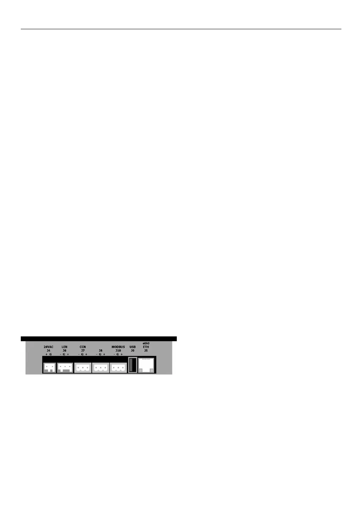
3.4 - SmartVu
TM
connections
Connections are located on the bottom of the main controller.
■ The control oers communication protocols such as LEN, CCN
(Carrier Comfort Network), Modbus, or BACnet.
■ It is possible to enable and disable end of line resistors via the
System menu (see section 5.6).
■ One Ethernet port allows for TCP/IP communication or BMS
(Building Management System) connection.
3.5 - Pressure transducers
The control implements three types of pressure transducers, i.e.
low pressure, high pressure, and water pressure type. The water
pressure transducer is used only in case of units tted with the
hydronic module.
■ Discharge pressure transducer (high pressure type)
This transducer measures the discharge pressure in the circuit.
It is used to control condensing pressure or high pressure load
shedding. Discharge pressure sensor is mounted on the
discharge line piping of the circuit.
■ Suction pressure transducer (low pressure type)
This transducer measures the suction pressure in the circuit.
It is used to control EXV, evaporating pressure (in heating
mode) and monitor suction pressure safeties related to the
compressor operating envelope. Suction pressure sensor is
located on the suction piping of the circuit.
■ Economizer pressure transducer (high pressure type)
This sensor measures the intermediary pressure between
suction and discharge pressure sensors. It is used for EXV
economizer control. The sensor is mounted on the plate
exchanger on the economizer side.
■ Water pressure transducer
As an option (hydronic module), this sensor is used to monitor
the water pressure. The pump is protected against cavitation
(low pump entering pressure).
3.6 - Temperature sensors
Temperature sensors constantly measure the temperature of
various components of the unit, ensuring the correct operation of
the system.
■ Water heat exchanger entering and leaving water
temperature sensors
The water heat exchanger entering and leaving water
temperature sensors are used for capacity control and safety
purposes. These water temperature sensors are installed in
the entering and leaving side.
■ Suction temperature sensors
Suction temperature sensors are used to control temperature
at the compressor inlet line in order to ensure correct capacity
control management.
■ Economizer suction temperature sensor
This sensor is used for economizer EXV control. The sensor
measures the temperature of gas in the plate exchanger on
economizer side before entering the compressor economizer
port.
■ Outdoor air temperature sensor
This sensor measures the outdoor air temperature used to
determine the summer mode (see section 6.6.3) or calculate
the control point provided that the oset (reset) is based on the
outdoor air temperature reading (see section 6.5.2).
■ Defrost temperature sensors
These sensors are used to determine the end of the defrost
cycle for a circuit. Units with two fans have two defrost sensors,
one sensor per each fan.
■ Domestic hot water temperature sensor (optional)
This sensor is used to measure the water tank temperature and
control the heating request.
■ Master/Slave water sensors (optional)
These sensors measure the common water temperature in the
master/slave system capacity control. They are installed only
in the case of master/slave units.