10
3.9 - RS485 wiring (best practice)
For RS485 ports, one of the following cables can be used:
■ two twisted pairs + a shield (RECOMMENDED)
■ three wires + a shield
Note that “+” and “-” are communication signals and they are from
the same twisted pair.
The signal ground could be a single wire or a twisted pair and it should
be connected to the “C” pin of J10 (Modbus RTU) or J7 (CCN).
This wire is required so that all nodes on the bus share a common
ground reference connection.
If a shield is used, then the shield cable should be properly
terminated and connected as short as possible at ONLY one
end to the chassis ground (4.3-inch controllers).
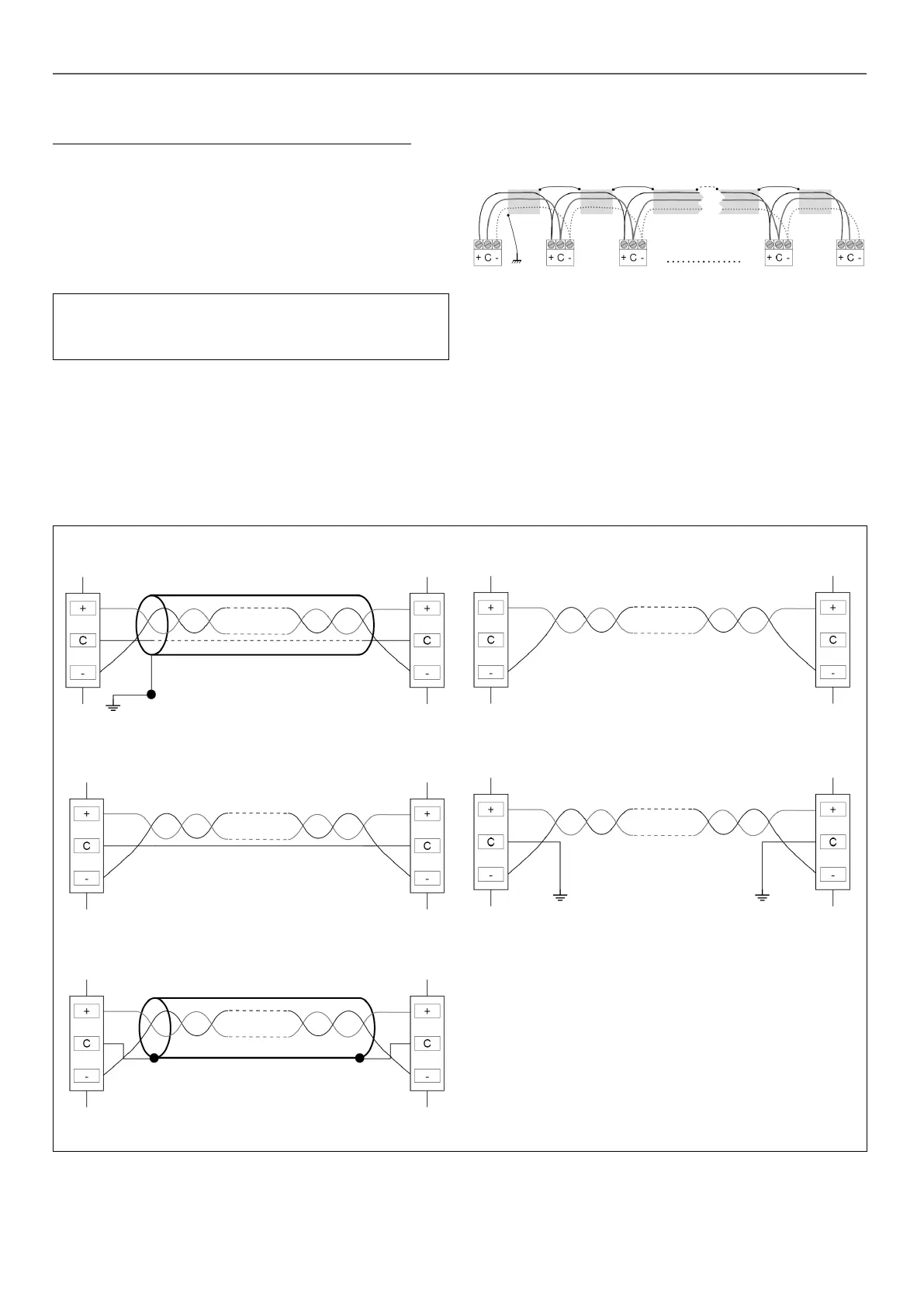
3.9.1 - RS485 wiring: 4.3-inch controller
The following diagrams illustrate possible RS485 wiring schemes
for 4.3-inch controllers.
The rst wiring scheme is the best option (RECOMMENDED), but
the second or the third wiring can also be used.
3 - HARDWARE DESCRIPTION
No.1 RS485 wiring diagram (RECOMMENDED)
No. 2 RS485 wiring diagram (CORRECT)
No. 3 RS485 wiring diagram (CORRECT)
No. 4 RS485 wiring diagram (INCORRECT - Do not use!)
No. 5 RS485 wiring diagram (INCORRECT - Do not use!)
3.9.2 - RS485: Daisy chain conguration
The following illustration shows proper 3-wire cable with a shield
in a daisy chain conguration.
B
C
D
Legend
B
Shield
C
Keep shield continued
D
Connect shield to earth ground only at one point
End of Line Resistor: Termination is only needed when running at
bus at very high speed over long distances.
The speed of the bus and the cable distance determine whether
termination is needed. It is meant to balance the bus to minimize
the ringing that may be caused by fast signals and the inductance
of the cabling.
At 9600 baud, termination will have little or no eect on the bus.