ii
LIST OF ILLUSTRATIONS
Figure Page
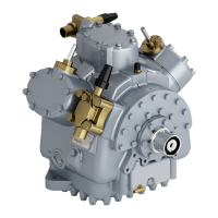
1-1 Model 05G Compressor 1-2.................................................
1-2 Suction & Discharge Valve 1-3...............................................
1-3 Oil Pumps 1-3.............................................................
1-4 Compressor Unloader --- Hot Gas Bypass 1-4..................................
1-5 Compressor Cylinder Head Unloaded --- Hot Gas Bypass 1-4.....................
1-6 Compressor Cylinder Head Loaded --- Hot Gas Bypass 1-5.......................
1-7 Compressor Cylinder Head (Unloaded) --- Suction Cutoff 1-5....................
1-8 Compressor Cylinder Head (Loaded) --- Suction Cutoff 1-6......................
1-9 Pressure-Operated Unloader Loaded Operation 1-6............................
1-10 Pressure-Operated Unloaded Unloaded Operation 1-6..........................
2-1 Removal of Piston Plug 2-1..................................................
2-2 Oil Level in Sight Glass 2-2..................................................
3-1 Cylinder Head & Valve Plate 3-1.............................................
3-2 Installing Suction Valves 3-2.................................................
3-3 Checking Suction Valve 3-2..................................................
3-4 Oil Pump and Bearing Head Assembly 3-2.....................................
3-5 Low Profile Gear Oil Pump 3-2..............................................
3-6 Gear Oil Pump 3-3.........................................................
3-7 Vane Oil Pump 3-4........................................................
3-8 Shaft Seal 3-5.............................................................
3-9 Shaft Seal Removal 3-5.....................................................
3-10 Bottom Plate Removal 3-5..................................................
3-11 Bottom Plate and Oil Strainer Removed 3-6...................................
3-12 Piston Rings Removed 3-6..................................................
3-13 Connecting Rod, Piston, and Pin 3-6..........................................
3-14 Seal End Main Bearings 3-7.................................................
3-15 Contoured Piston 3-7.......................................................
3-16 Installing Piston Rod Assemblies and Seal End Thrust Washer 3-7.................
3-17 Piston Rings 3-7...........................................................
3-18 Installing Pistons 3-8.......................................................
3-19 Installing Suction Strainer 3-8...............................................
3-20 Piston Dimension (Wear Limits) 3-10..........................................
3-21 Compressor Exploded View 3-11..............................................
LIST OF TABLES
Tabl e Page
3-1 Torque Values 3-9..........................................................
3-2 Wear Limits 3-10...........................................................

 Loading...