1-1
SECTION 1
DESCRIPTION
1.1 INTRODUCTION
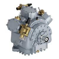
This operation and service manual covers the Carrier
Transicold Model 05G compressors. These compressors
are designed for refrigeration (trailer) or air conditioning
(bus & rail) applications. (See Figure 1-1) The following
table list the special tools for the 05G compressors.
PART NO.
SPECIAL TOOLS
07-00219 Wrench, Compressor Sight Glass
07-00223 Pliers, Compressor Unloader Ring
07-00240-01
Wrench, Spanner
(for Housing Mounted Clutch)
07-00241
Rotor Installation Tool
(for Housing Mounted Clutch)
07-00242-01
Bearing Retaining Nut Socket
(3.5
""
)
(Housing Mounted Clutch)
07-00242-02
Bearing Retaining Nut Socket
(3
""
)
(for Housing Mounted Clutch)
07-00260-00 Acid Test Kit
07-00265-01 To ta lt es t Ki t ( Pa ck ag e of 1)
07-00266-00 Replacement Tubes for Totaltest Kit
58-00869-00
Filter, Felt (Suction Sock for
System Clean Up)
1.2 GENERAL DESCRIPTION
The Model 05G compressors are of the open-drive
reciprocating type. A crankshaft, connecting rods,
pistons, and reed type valves accomplish vapor
compression. Compressor wear is minimized by splash
lubrication and by force feed lubrication. There are three
types of oil pumps (Vane, Gear and Low Profile Gear)
driven directly from the end of the compressor
crankshaft. (See Figure 1-3)
CAUTION
The gear oil pump must be set to rotate in the
same direction as the crankshaft. (Refer to
section 3.4)
The tapered end of the crankshaft, which extends
outside the crankcase, is adaptable to a variety of direct
drive or belt---driven clutch mechanisms. A mechanical
seal prevents refrigerant l eakage where the rotating shaft
passes through the crankcase.
The compressor is equipped with flanges for
connecting suction and discharge service valves.
Connections are also provided for pressure gauges and
safety cutout switches. Sight glasses installed on both
sides of the crankcase, provides a means for checking oil
level in the compressor crankcase. A drain plug facilitates
draining of oil from the crankcase and an oil fill plug
enables addition of oil when necessary. A bottom plate
provides access through the bottom of the crankcase for
maintenance.
WARNING
Do not operate compressor unless suction and
discharge service valves are o pen.
Capacity of the Model 05G compressor is
determined by piston displacement and clearance,
suction and discharge valve size, compressor speed,
suction and discharge pressure, type of refrigerant, and
unloader valves.
1.3 COMPRESSOR REFERENCE DATA
Model
05G---37CFM 05G---41CFM
Displacement 37CFM 41CFM
No. Cylinders 6
Bore 50.8 mm (2.00 in)
Stroke
49.2 mm
(1.937 in)
54.36 mm
(2.14 in)
Weight 62 kg (137 lbs)
SPEED (RPM) FOR OIL PUMP
Vane 900 to 2200
Gear 500 to 2200
Low Profile Gear 500 to 2200
NOTE
The oils below are suitable for use with
evaporator temperatures above ---4 0˚F
( --- 4 0 ˚C).
Approved Oil for REFRIGERATION USE
(TRAILER)
Refrigerant Oil
R-12, R-22, R-500
or R-502
Zerol: 150 Synthetic
P/N 07-00274
Castrol Icematic: SW-68C
R-404A
Mobil Arctic: EAL 68
ICI: Emkarate RL68H
Approved Oil for AIR CONDITIONING USE
(BUS AND RAIL)
Refrigerant Oil
Calumet Refining: R030
R-12 or R-22
Tex ac o: WF6 8
Witco: 4GS Suniso
Castrol Icematic: SW-68C
R-134a
Mobil Arctic: EAL 68
ICI: Emkarate RL68H
Revised 10/96
 Loading...