ii
TA BLE OF CONTENTS (CONT’D)
Section Page
4 SERVICE (CONT’D) 4-1.....................................................
4.17 Removing the Conde nser Fan Motor 4-10........................................
4.18 Servicing the Evaporator Fan Blower Motor Assembly 4-11.........................
4.19 Replacing the Return Air Filte rs 4-11...........................................
4.20 Compressor 4-11.............................................................
4.20.1 Replacing the Compressor 4-11.........................................
4.20.2 Checking the Compressor Oil Level 4-12.................................
4.20.3 Adding Oil to the Installed Compressor 4-12..............................
4.20.4 Adding Oil to Service Re placement Compressor 4-13.......................
5ELECTRICAL
5.1 Introduction 5-1............................................................
LIST OF ILLUSTRATIONS
Figure Page
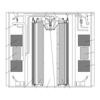
1-1 Evaporator Assembly - Top View 1-2..........................................
1-2 Condenser Assembly - Top View 1-3..........................................
1-3 Electrical Control Panel C omponents for Models with Rotron Brushless Motors 1-4..
1-4 Reheat Coolant Valve 1-9...................................................
1-5 Heater Coolant Flow Dia gram 1-9............................................
1-6 Refrigeration Cycle Diagram 1-10.............................................
2-1 Temperature Controller Sequence During Cooling Mode 2-2.....................
2-2 Temperature Controller Sequence During Cooling with Reheat Mode 2-2..........
2-3 Temperature Controller Seq uence During Heating Mode 2-3.....................
2-4 Cooling Cycle - High Speed Vent Mode Operation 2-4..........................
2-5 High Spe ed Unloaded (2-cylinder operation) Cool Mode Opera tion 2-5............
2-6 High Speed Semi-loaded (4-cylinder operation) Cool Mode Operation 2-6.........
2-7 High Spe ed Fully Loaded (6-cylinder operation) Cool Mode Operation 2-7.........
2-8 High Spe ed Unloaded (2-cylinder operation) Cool with Re heat Mode Ope ra tion 2-8.
2-9 Heating Cycle - Low Speed Heat Mode Operation 2-9...........................
4-1 Suction or Discharge Servi ce Valve 4-1........................................
4-2 Gauge Manifold Set 4-2....................................................
4-3 Evacuation Manifold 4-4....................................................
4-4 Evacuation Set-Up 4-5......................................................
4-5 Filter Drier Removal 4-6....................................................
4-6 Checking High Pressure Switch 4-6...........................................
4-7 Thermostatic Expansion Valve 4-7............................................
4-8 Thermostatic Expansion Valve Bulb and Thermocouple 4-8......................
4-9 Reheat Coolant Valve Assembly 4-9..........................................
4-10 Liqui d Line Solenoid Valve - Alco 4-10.........................................
4-11 Compressor Oil Charge Connections 4-13......................................
4-12 Compressor - Model O5G 4-13...............................................
5-1 Electrical Wiring Schematic Diagram (68RF50 with Rotron Brushless Motors),
Dwg. No. C-070-935, Rev C 5-2.............................................
 Loading...

