Do you have a question about the Carrier Transport Air Conditioning and is the answer not in the manual?
Manual covers installation procedures for Carrier Transport Air Conditioning split systems.
General precautions for installation, operation, and service.
Guidelines for immediate medical attention after an injury.
Precautions for safe operation, including eye protection and tool safety.
Precautions for safe installation, tool usage, and handling of refrigerants.
Warnings against modifying evaporator assemblies and handling blower wheels.
Cautions regarding sealing, hardware, and structural integrity during installation.
Cautions regarding fitting installation, routing, and electrical connections.
Cautions regarding hardware, drilling, lubricants, and tie-wraps.
Manual purpose, scope, and general advice for quality installations.
Definition of air conditioning functions: cooling, dehumidification, filtration.
Explanation of system naming conventions and model identification.
Location and importance of model and serial number data tags.
Information on the system requirements label and its placement.
Key components like compressor, condenser, evaporator, and their functions.
Components managing refrigerant flow and state, like expansion valve and filter drier.
Thermostat, clutch, and refrigerant's role in the system.
Explains the R-134a system operation, heat transfer, and state changes.
Illustrates the path of refrigerant through the system components.
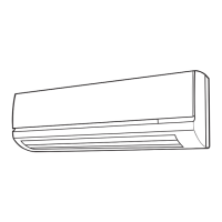
Describes evaporators' role in heat transfer and mounting options.
Lists specifications for GEN 4 and GEN 5 evaporator models.
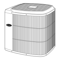
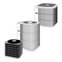
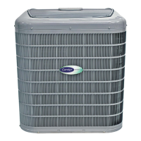
Explains condensers' role in heat rejection and placement options.
Lists various condenser models and their specifications.
Procedures for checking cartons, contents, blower wheels, and for damage.
Overview of evaporators' function, location, and mounting.
Description, location, cap plugs, and blower wheel handling for evaporators.
Step-by-step installation procedures for rear-mounted evaporators.
Provides dimensions for GEN 4 and GEN 5 evaporator models.
Marking the center of the bus ceiling and wall for template placement.
Drilling pilot and final holes for mounting hardware.
Securing the evaporator, sealing reinforcing rails, and preventing condensate drip.
Connecting hoses and harnesses, and routing them if not previously done.
Installing the evaporator cover, addressing ceiling gaps with trim strips.
Installing the return air grill and cleaning the unit and bus interior.
Requirements for return air flow when installing evaporators in luggage compartments.
Specific installation steps for the EM-3 evaporator, noting threaded rod usage.
Warning against modifying the EM-3 evaporator top panel due to structural risks.
Step-by-step guide for installing side-mounted evaporator assemblies.
Recommendation to use two roof bows for securing mounting rails.
Steps for installing the EM-9 ducted evaporator, referencing Section 2.3.
Information on ducting, hoses, and harness routing for EM-9.
Advises OEM installation due to weight and size, recommending contacting technical service.
Describes In-Wall evaporators and the need to remove wall sections for installation.
Installation procedures for rear-mounted In-Wall evaporators.
Tables providing dimensions for IW-1, IW-2, and IW-14 models.
Warning to avoid cutting bus structure rails or wiring harnesses during In-Wall unit installation.
Removing insulation and supporting wiring during In-Wall installation.
Relocating ground screw and cutting access holes for routing hoses and drain lines.
Notching an area for drain line elbows to ensure proper drainage.
Mounting the In-Wall evaporator, connecting harness, and grounding.
Caution on starting fittings by hand to avoid cross-threading and ensure the block valve does not move.
Key considerations for front-mounted In-Wall evaporators: hose routing, drain lines, driver visibility.
Warning against routing hoses or cables where they impair driver visibility.
Caution against using tie-wraps to secure moving parts; use insulated clamps.
Floor-mounted units for ambulances/armored vehicles; contact technical service for instructions.
After-market unit for vehicle dashes; contact technical service for instructions.
Overview of condenser function and primary locations.
Guidance on placement, protection from wheel-sling, and clear airflow.
Discusses condenser placement, stacking options, and lists models/specifications.
Procedures for installing skirt-mounted condenser assemblies.
Step-by-step guide for skirt-mounted condenser installations.
Drilling pilot holes for condenser mounting.
Caution to ensure no obstructions are present before drilling through the bus floor.
Illustrates typical installation methods for skirt-mounted condensers.
Details for installing the CM-5 condenser in the bus skirt.
Notes on the number of bolts required for CM-5 installation due to its size and weight.
Step-by-step procedures for installing KR rooftop condensers.
Rooftop condenser must contact the roof center; consult factory if needed.
Tracing feed-thru plate locations and marking cut-out for bus roof and ceiling.
Procedures for installing KR2/3 rooftop condensers.
Information on different mounting bracket and feed-thru plate styles.
Routing refrigerant hoses between side-mounted evaporators and rooftop condensers.
Condenser assemblies must be properly installed with graded hardware.
Importance of refrigerant hose and fitting connections for system operation.
Careful planning for hose routing to avoid heat/edges and importance of service loops.
Ensuring system independence and using mineral oil for connections.
Recommended use of Carrier's "Quick-Click" hose and fittings.
Steps for cutting, sliding, and installing fitting clamps onto hoses.
Lubricating O-rings and inserting fittings into hoses.
Pre-drilling checks for obstructions and drilling pilot and final holes for hoses.
Caution to use a drill stop when drilling into vehicle walls to prevent wire damage.
Installing hose covers and routing hoses and harnesses.
Procedures for routing evaporator hoses outside the bus wall.
Determining the side for routing hoses and planning routes considering obstacles.
Positioning and marking hose cover backs to outline hole placement.
General guidelines for routing hoses and harnesses in the chassis area.
Precautions for routing hoses in the engine compartment, avoiding heat and sharp edges.
Warning against substituting fittings/hose and reiterating mineral oil use.
Table of torque specifications for refrigerant fittings based on size and material.
Importance of electrical harness routing for system performance.
Details on electrical kits, harnesses, and safe connection.
Precautions for protecting wiring and ensuring independence for dual systems.
Grounding procedure for Gen 4 evaporators to the chassis rail.
Grounding procedure for Gen 5 evaporators to the chassis rail or roof frame.
Description of manual control options and placement.
Location requirements and components of the electrical control panel.
Protecting cables routed through the firewall with grommets.
Torque values for circuit breakers, mounting screws, and terminal strips.
Description of the Total Control system's keypad display and electrical panel.
Details on the wiring and components of the Total Control electrical panel.
Requirements for operating the system, including engine and manual.
Overview of mount kits and compressors, their purpose and alignment.
Procedures for installing Carrier Transport Air Conditioning mount kits and compressors.
Torque values for metric bolts based on grade and size.
Torque specifications for electrical panel components.
Guidelines for proper drive belt installation and maintenance.
Essential steps for ensuring correct pulley alignment for belt life.
Recommended belt tensions for alternators and compressors, including run-in periods.
Methods and tools for measuring belt tension accurately.
Proper positioning of the compressor for lubrication system function.
Instructions for adding compressor oil and warnings about mixing incompatible oils.
Emphasizes using only specified oil to avoid voiding compressor warranty.
Importance of evacuation for removing air and moisture from the system.
Essential tools required for system installation and servicing.
Steps for preparing the system and tools, and the procedure for evacuating the system.
Steps to prepare a new or exposed manifold gauge set for service.
Procedures for connecting and disconnecting the manifold gauge set.
Caution to bring the manifold gauge set to suction pressure before disconnecting.
Process of introducing refrigerant and oil for optimal performance.
Importance of correct R134a and oil charge for system performance and longevity.
Warning against liquid charging into the suction side due to compressor damage risk.
Impact of aftermarket evaporators on refrigerant charge and CM-2 condenser tie-in advice.
Emphasizes using only specified oil to avoid voiding compressor warranty.
Steps for adding refrigerant charge to the system, including vacuum and scale use.
Purpose of leak checking for system integrity and performance.
Importance of micron gauges and nitrogen for leak detection.
Warning against using nitrogen cylinders without a pressure regulator.
Procedures for performing refrigerant leak checks on the system.
Importance of registering the system for warranty coverage.
Steps for dealers and consumers to register units online.
Information on obsolete paper warranty registration cards.
Importance of the checkout procedure for ensuring installation quality.
Fields for general vehicle info and checklist items for the engine area.
Checklist for condenser mounting, grounding, and airflow.
Checklist items for evaporator mounting, hose routing, and grounding.
Checklist for proper routing, protection, and securing of hoses and harnesses.
Checklist items related to system operation and installer understanding.
Recording system pressures, temperatures, and charges after operation.
Section for recording final system data and installer information.
Step-by-step guide for completing the system requirements label.
| Brand | Carrier |
|---|---|
| Model | Transport Air Conditioning |
| Category | Air Conditioner |
| Language | English |