1-1
SECTION 1
DESCRIPTION
1.1 INTRODUCTION
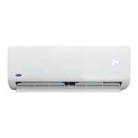
Thismanualcontainsoperatingdata,electricaldata,
and service instructions for the 68RF50 NEOPLAN-LA
air conditioning, heating and ventilation systems shown
in the model chart below.
The68RF50unitsaretwopiecesystemsconsistingof
condenser and evaporator assemblies. The units are
installedontheroofofthebus.Theseunitsinte rfacewith
thebus’compressor,floorheater, and pumpto providea
full air conditioning, heating and ventilation system.
The 68RF50 units are equipped with R-134a
refrigerant.
All control syste ms are powered by 24-vdc supplied
by the bus battery and alternator or alternate source.
Operation of the 68RF50 units is controlled
automatically by the temperature controller which
maintains the vehicles interior temperature at the
desired setpoint.
The uni ts are equipped with a reheat/cycling clutch
switch to give the operator the option between cooling
control actions. In the cycling clutch control operation,
the compressor cycles on and off to control vehicle
interior temperature. When the switch is in REHEAT
position, t he coolant valve opens and closes on
thermostat command to control vehicle interior
temperature while the air conditioning mode continues
to operate.
Ta ble 1-2 shows additional manuals available for
servicing the 68RF50 units.
Table 1-1. Model Chart
MODEL
SERIES DESCRIPTION
68RF50 NEOPLAN-LA Roof Mounted Three Condenser Fan
Table 1-2. Additional Support Manuals
MANUAL/FORM NO.
EQUIPMENT COVERED TYPE OF MANUAL
T-199 05G Bus Compressor Operation and Service
T-200 05G Bus Compressor Parts List

 Loading...