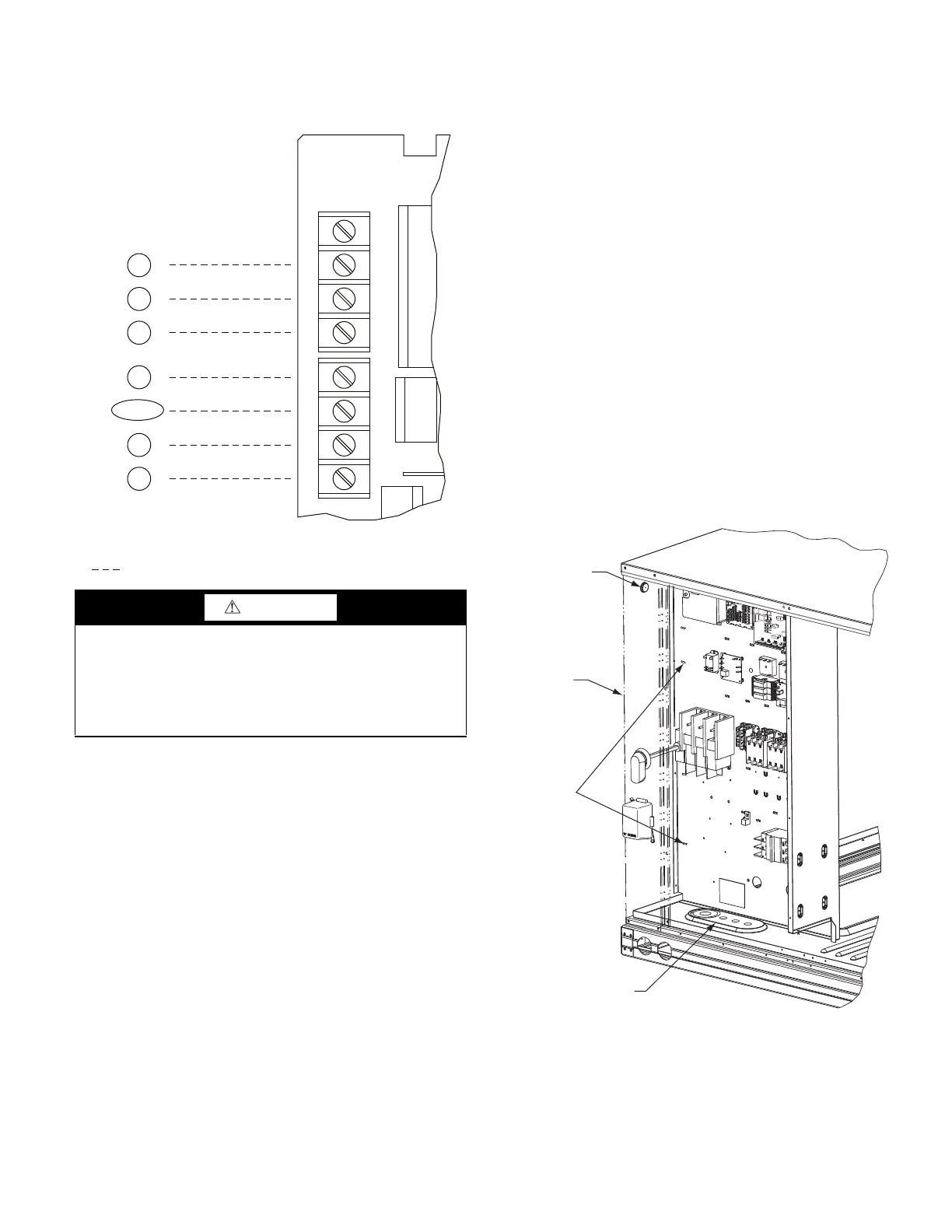
31
low voltage wire and the high voltage circuit. Route the low volt-
age wire to the central terminal board. See Fig. 40.
NOTE: If utilizing the through the base connections, route the low
voltage wire through the wire ties to the central terminal board.
Fig. 40 — Typical Low-Voltage Control Connections
Heat Anticipator Settings
Set heat anticipator settings at 0.14 amp for the first stage and
0.14 amp for second-stage heating.
Transformer Connection for 208-v Power Supply
All units except 208/230-v units are factory wired for the voltage
shown on the nameplate. If the 208/230-v unit is to be connected
to a 208-v power supply, the control transformer must be rewired
by moving the black wire with the
1
/
4
-in. female spade connector
from the 230-v connection and moving it to the 208-v
1
/
4
-in. male
terminal on the primary side of the transformer. Refer to unit label
diagram for additional information.
Humidi-MiZer
®
Control Connections
HUMIDI-MIZER – SPACE RH CONTROLLER
NOTE: The Humidi-MiZer system is a factory installed option
which is available for size 17, 20, 24 and 28 units equipped with
RTPF condenser coils.
The Humidi-MiZer dehumidification system requires a field-sup-
plied and installed space relative humidity control device. This de-
vice may be a separate humidistat control (contact closes on rise in
space RH above control setpoint) (see Fig. 42) or a combination
thermostat-humidistat control device such as Carrier’s EDGE
®
Pro Thermidistat (see Fig. 43) with isolated contact set for dehu-
midification control. The humidistat is normally used in applica-
tions where a temperature control is already provided (units with
PremierLink™ control).
To Connect the Carrier Humidistat (HL38MG029):
1. Route the humidistat 2-conductor cable (field-supplied)
through the hole provided in the unit corner post.
2. Feed wires through the raceway built into the corner post (see
Fig. 41) to the 24-v barrier located on the left side of the con-
trol box. The raceway provides the UL-required clearance
between high-voltage and low-voltage wiring.
3. Use wire nuts to connect humidistat cable to two PINK leads
in the low–voltage wiring as shown in Fig. 44.
To connect the Thermidistat device (33CS2PPRH- 01)
1. Route the Thermidistat multi-conductor thermostat cable
(field-supplied) through the hole provided in the unit corner
post.
2. Feed wires through the raceway built into the corner post (see
Fig. 42) to the 24-v barrier located on the left side of the con-
trol box. The raceway provides the UL-required clearance
between high-voltage and low-voltage wiring.
3. The Thermidistat has dry contacts at terminals D1 and D2
for dehumidification operation (see Fig. 45). The dry con-
tacts must be wired between CTB terminal R and the PINK
lead to the LTLO switch with field-supplied wire nuts.
Refer to the installation instructions included with the Car-
rier Edge Thermidistat device for more information.
Fig. 41 — Field Control Wiring Raceway
CAUTION
UNIT DAMAGE HAZARD
Failure to follow this caution may cause a short circuit.
Carefully check the connection of control conductor for indoor
fan control at terminal G. Connecting the indoor fan lead to ter-
minal C will cause a short circuit condition, which can cause
component damage inside the unit or at the thermostat.
C
W2
G
W1
R
Y1
TYPICAL
THERMOSTAT
CORRECTIONS
O/B/Y2
(SEE NOTE)
NOTE: Typical multi-function marking. Follow manufacturer’s configuration
instructions to select Y2.
Field Wiring
CENTRAL
TERMINAL
BOARD
W1
Y2
Y1
R
W2
G
C
X
W1
Y2
Y1
R
W2
G
C
X
T–STAT
SEE
CAUTION
RUBBER
GROMMET
CORNER
POST
WIRE
TIES
THRU THE BASE
CONNECTION

 Loading...


