2
Carrier means Top Quality
and Reliability
Each component utilized in the
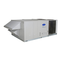
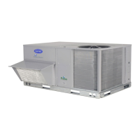
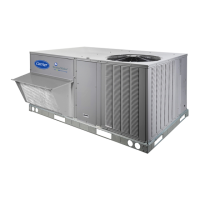
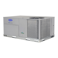
Weathermaster
®
Series is designed
and tested for a minimum of 15 years
operation under the harshest
conditions.
Every unit is thoroughly run tested at
the factory in each operating mode
and evacuated prior to final charging.
Every coil is leak tested with helium
particles. Automated run testing allows
accurate, undisputed tests and mea-
surements which are second to none in
the industry.
Each unit contains a factory print-
out indicating tested pressures,
amperages, dates, and inspectors, pro-
viding certification of the unit’s status
at the time of manufacture.
Units are equipped with valuable
safety controls designed to monitor
and protect for the life of the unit. The
standard safeties include:
• low-pressure/loss-of-charge switch
• high-pressure switch
• freeze-protection thermostat
• internal compressor overload
• exclusive Carrier Cycle-LOC™
circuit board that provides anti-
compressor cycling
• refrigerant filter drier
The cabinet is constructed of galva-
nized steel, bonderized, and coated
with a prepainted baked enamel finish.
The paint finish is a non-chalking type,
and is capable of exceeding Federal
Test Method Standard No. 141
(Method 6061) 500-Hour Salt Spray
Test. In addition, all cabinet panel inte-
rior surfaces are primed, allowing the
entire unit to have longer life and a
more attractive appearance.
Table of contents
Page
Features/Benefits . . . . . . . . . . . . . . . . . . . . . . . . . . . . . . . . . . . . . . . . . . 1-6
Model Number Nomenclature. . . . . . . . . . . . . . . . . . . . . . . . . . . . . . . . . . . 6
ARI capacities . . . . . . . . . . . . . . . . . . . . . . . . . . . . . . . . . . . . . . . . . . . . . . 7
Physical Data . . . . . . . . . . . . . . . . . . . . . . . . . . . . . . . . . . . . . . . . . . . . 8-11
Options and Accessories . . . . . . . . . . . . . . . . . . . . . . . . . . . . . . . . . . . 12-16
Base Unit Dimensions . . . . . . . . . . . . . . . . . . . . . . . . . . . . . . . . . . . . . 17,18
Accessory Dimensions . . . . . . . . . . . . . . . . . . . . . . . . . . . . . . . . . . . . . 19,20
Selection Procedure. . . . . . . . . . . . . . . . . . . . . . . . . . . . . . . . . . . . . . . 21-23
Performance Data . . . . . . . . . . . . . . . . . . . . . . . . . . . . . . . . . . . . . . . . 24-50
Electrical Data . . . . . . . . . . . . . . . . . . . . . . . . . . . . . . . . . . . . . . . . . . . 51-54
Typical Piping and Wiring . . . . . . . . . . . . . . . . . . . . . . . . . . . . . . . . . . 55,56
Controls . . . . . . . . . . . . . . . . . . . . . . . . . . . . . . . . . . . . . . . . . . . . . . . 57-64
Application Data . . . . . . . . . . . . . . . . . . . . . . . . . . . . . . . . . . . . . . . . . 65-69
Typical Wiring Schematic. . . . . . . . . . . . . . . . . . . . . . . . . . . . . . . . . . . 70,71
Guide Specifications . . . . . . . . . . . . . . . . . . . . . . . . . . . . . . . . . . . . . . 72-75

 Loading...
