14
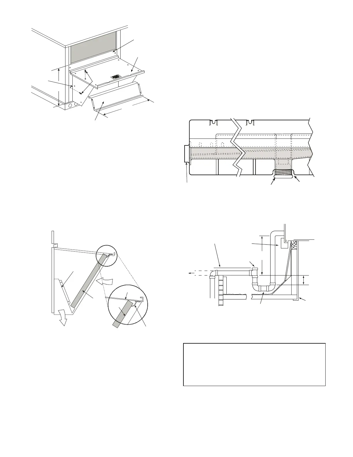
Fig. 14 — Economizer Hood Construction
3. Remove the shipping tape holding the economizer baro-
metric relief damper in place (economizer only).
4. Insert the hood divider between the hood sides. See
Fig. 14 and 15. Secure hood divider with 2 screws on
each hood side. The hood divider is also used as the bot-
tom filter rack for the aluminum filter.
5. Open the filter clips which are located underneath the
hood top. Insert the aluminum filter into the bottom filter
rack (hood divider). Push the filter into position past the
open filter clips. Close the filter clips to lock the filter
into place. See Fig. 15.
6. Caulk the ends of the joint between the unit top panel and
the hood top.
7. Replace the filter access panel.
Fig. 15 — Economizer Filter Installation
Step 9 — Install External Condensate Trap and
Line
The unit has one
3
/
4
-in. condensate drain connection on the
end of the condensate pan and an alternate connection on the
bottom. See Fig. 16. Unit airflow configuration does not de-
termine which drain connection to use. Either drain connec-
tion can be used with vertical or horizontal applications.
When using the standard side drain connection, ensure the
red plug in the alternate bottom connection is tight. Do this
before setting the unit in place. The red drain pan can be
tightened with a
1
/
2
-in. square socket drive extension.
To use the alternate bottom drain connection, remove the
red drain plug from the bottom connection (use a
1
/
2
-in.
square socket drive extension) and install it in the side drain
connection.
Fig. 16 — Condensate Drain Pan (Side View)
The piping for the condensate drain and external trap can
be completed after the unit is in place. See Fig. 17.
Fig. 17 — Condensate Drain Piping Details
B
TOP
PANEL
INDOOR COIL
ACCESS PANEL
19 1/16″
SCREW
HOOD DIVIDER
LEFT
HOOD
SIDE
33 3/8″
(848 mm)
(483 mm)
DIVIDER
BAROMETRIC
RELIEF
CLEANABLE
ALUMINUM
FILTER
FILTER
HOOD
FILTER
CLIP
OUTSIDE
AIR
IMPORTANT: All units must have an external trap for con-
densate drainage. Install a trap at least 4 in. (102 mm) deep
and protect against freeze-up. If drain line is installed
downstream from the external trap, pitch the line away
from the unit at 1 in. per 10 ft (25 mm in 3 m) of run. Do
not use a pipe size smaller than the unit connection (
3
/
4
-in.).
DRAIN
(FACTORY-INSTALLED)
PLUG
CONDENSATE PAN (SIDE VIEW)
STANDARD
SIDE DRAIN
ALTERNATE
BOTTOM DRAIN
NOTE: Trap should be deep enough to offset maximum unit static
difference. A 4-in. (102 mm) trap is recommended.
MINIMUM PITCH
1˝ (25 mm) PER
10´ (3 m) OF LINE
BASE RAIL
OPEN
VENT
TO ROOF
DRAIN
DRAIN PLUG
ROOF
CURB
SEE NOTE
3˝ (76 mm)
MIN
 Loading...


