Page 4 of 8 SA-380-10 Installation Instructions
07/29/05 CP4964A
UNPACKING
Inspect contents for shipping damage. If found alert carrier immediately
. Contents should in-
clude unit with attached microphone, mounting bracket, microphone bracket with 2 screws,
mounting hardware and these instructions. Contact supplier immediately if any components are
missing.
MOUNTING
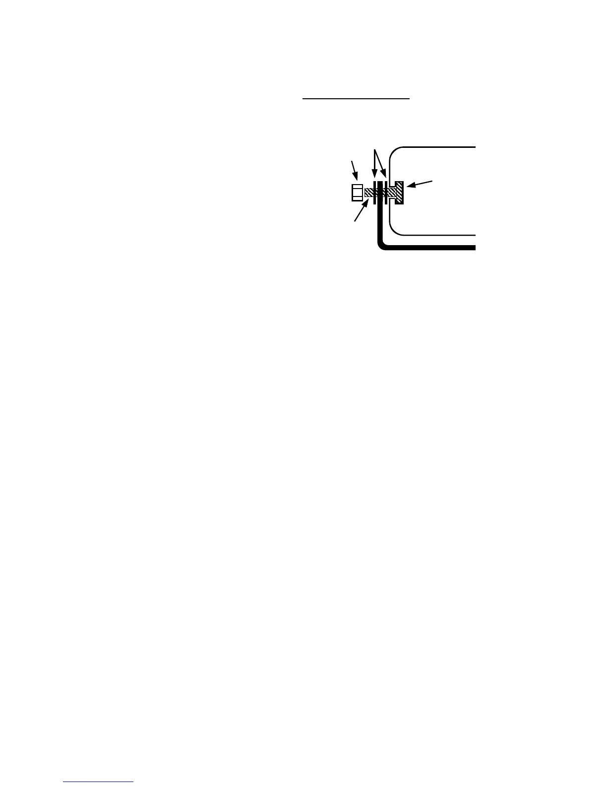
The mounting bracket supplied can be installed above
or below the unit. Mounting bolts slide into channels
on each side of the case. Lockwashers should be
used between the case and bracket as well as be-
tween the bracket and nut. Choose a mounting loca-
tion convenient to the operator and away from any air
bag deployment areas. Inspect behind mounting area
for clearance. Assure adequate ventilation to prevent
overheating. Consider wire routing and access to
connections, as well as microphone bracket placement.
Install mounting bracket to vehicle using 1/4" hardware
(not supplied).
OPTION SWITCHES
An internal 8-position DIP switch on the circuit board may be changed to select various options.
Accessing Option Switches - the DIP switch is located just behind the front panel of the ampli-
fier. Use a 7/64” allen wrench to remove the 4 corner screws and front panel. Be careful not to
unplug internal microphone connection.
1 (AUX_P) Auxiliary Input Polarity - The auxiliary input is normally activated by positive. Turn
switch off to activate with negative.
2 (AUX_F) Auxiliary Function - The auxiliary input normally activates Manual siren tone while in
standby, turn switch on to activate Horn tone instead.
3 (HRC) Horn Ring Cycler 2 (HRC2) - While the siren is in standby, the auxiliary input can cycle
through Wail, Yelp, and Phaser tones by repeatedly activating the auxiliary input. Turn switch on
to enable this feature. See OPERATION section for further details.
4 (T-T) Two-Tone - Two-Tone replaces Phaser tone by turning on switch.
5 (P_I) Phaser Disable - Phaser and Two-Tone tones are disabled by turning on switch.
4 & 5 Siren Tone Disable - Disable all siren tones (except Horn) by turning switch 4 and 5 on.
6 (H_I) Horn Disable - Horn tone is disabled by turning on switch.
7 (SM) Short Manual - The Manual siren tone will normally die out and stop when activation is
released. Turn switch on to have the Manual siren tone stop immediately.
8 (INST_ON) Instant On - The Enable input is normally required to turn on the unit. With this
switch on, the siren controls will instantly power on the unit even without the Enable input active.
See OPERATION section.
Lockwashers
Nut
Channel
(from rear)
Bolt
Bracket