SA-380-10 Installation Instructions Page 5 of 8
CP4964A 07/29/05
ELECTRICAL CONNECTIONS
Electrical connections to the unit are made using common
butt splices (not supplied) attached to the leads provided.
A label on the unit identifies the lead function. The power
supply of the unit must be capable of delivering peak cur-
rents up to 50 amps for adequate short circuit protection
and reliable operation. The preferred source is directly at
the vehicle battery. The unit is provided with an in-line
fuse. Failure to adequately crimp splices can result in
improper operation or burning the wire.
Wire Size and Termination - The diagram shows the mini-
mum wire size used for each connection, along with recom-
mended lead color. If the wire is longer than 10 ft. use the
next larger wire size. Use only high quality crimp connec-
tors for installation on the vehicle. Tape insulate lead to
prevent accidental shorting and activation.
Siren Enable Connection (orange lead) - This is like a power switch for the unit. Connect to a
positive circuit controlled by the vehicle ignition switch, usually a terminal at the vehicle fuse block.
Permanent power connection is not recommended as this keeps unit on unattended and may
drain battery.
Note: The Siren enable lead may not be necessary if Instant On option is used. See OPTION
SWITCHES section.
Auxiliary Input Connection (violet lead) - A momentary input typically connected to the horn
ring of the vehicle. See Auxiliary Polarity under OPTION SWITCHES section for proper activa-
tion polarity. The orange Siren Enable lead connection is required for the Auxiliary Input to func-
tion when the rotary switch is in Standby.
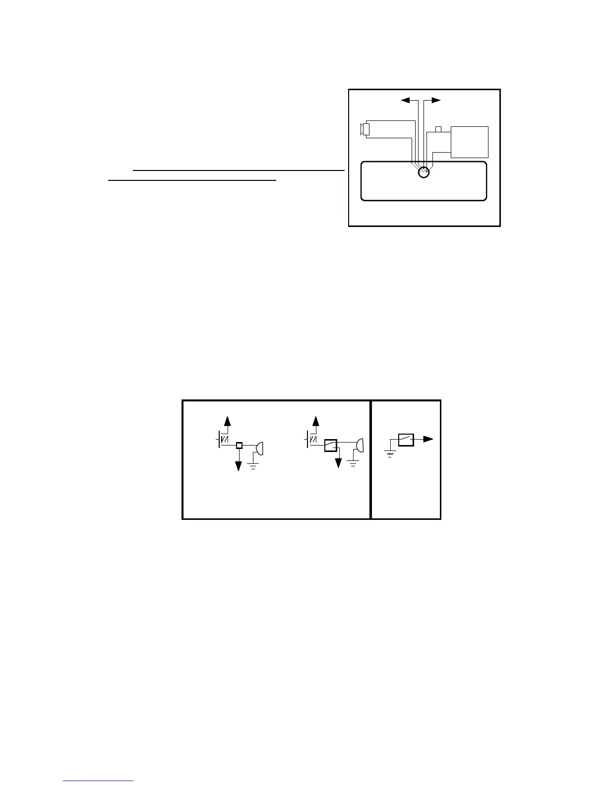
CONNECTIONS AT REAR OF UNIT
(2) #18 AWG BRN
#22 AWG ORG
Siren Enable
#14 AWG
BLK
#14 AWG RED
With in-line fuse
+
BAT
-
#22 AWG VIO
Auxiliary Input
+VDC Switching examples
HORN
RING
SWITCH
+VDC
AUX
SPLICE
HORN
RING
SWITCH
+VDC
Added
SPDT
Switch
HORN
HORN
-VDC
switching
example
MOMENTARY
FOOT
SWITCH
AUX
AUX