SC-1022-20 Installation Instructions Page 3 of 8
CP5208A 1/3/20
SPECIFICATIONS
UNPACKING
Inspect contents for shipping damage. If found
alert carrier immediately.
Contact supplier immediately if any items are
missing.
INSTALLATION
Proper installation of the unit is essential for years of safe, reliable operation. Please read all
instruction before installing the unit. Failure to follow these instructions can cause serious dam-
age to the unit or vehicle and may void warranties.
SAFETY PRECAUTIONS
For the safety of the installer, vehicle operator, passengers and the community please observe
the following safety precautions. Failure to follow all safety precautions and instructions may
result in property damage, injury or death.
Qualifications - The installer must have a firm knowledge of basic electricity, vehicle electrical
systems and emergency equipment.
Hand Control Location - Locate the hand control for easy access by the vehicle operator. DO
NOT locate in air bag deployment area.
Amplifier Mounting - Flanges are provided for mounting (hardware not supplied). Assure clear-
ances before drilling in vehicle.
Wiring - Use wiring capable of handling the current required. Make sure all connections are tight.
Route wiring to prevent wear, overheating and interference with air bag deployment. Install and
check all wiring before connection to vehicle battery.
Testing - Test all siren functions after installation to assure proper operation. Test vehicle opera-
tion to assure no damage to vehicle.
Keep These Instructions - Keep these instructions in the vehicle or other safe place for future
reference. Advise the vehicle operator of the location.
Siren Section
Input Voltage 10 - 16 VDC (negative ground)
Input Current 8 AMPS (@14 VDC - single 100W speaker)
Standby Current Less than 50mA @ 14 VDC enabled, less than 5mA standby
Output Power 105 WATTS RMS MAX. (15 VDC - single 100W speaker)
Siren Frequency 700Hz - 1500Hz (Mechanical 700Hz - 1600Hz; Two-Tone and Horn = 435 & 585Hz)
Tones / Cycle Rates Horn Mechanical Wail Power C Yelp Phaser Two-Tone
109 CPS 5 CPM 13 CPM 100 CPM 190 CPM 15 CPS 60 CPM
High Voltage
Protection
16 - 18 VDC will cause siren output to cease, resumes at normal voltage
Short Circuit Current 50 AMPS (supply circuit must be capable of supplying this for 1 second)
Operating Temp. -15° F to +140°F
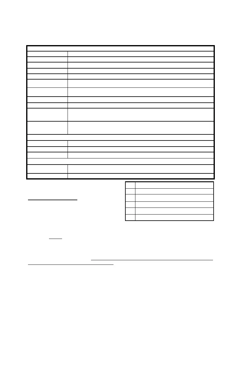
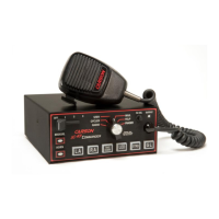
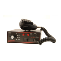
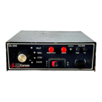
Controls Six Pushbutton switches for Mechanical, Wail, Yelp, Phaser, Manual, and Horn.
Auxiliary input programmable for positive or negative activation.
8-position DIP switch option selector.
Connections Removable 10-Pos Terminal Block: (2) Power, (2) Speaker, Auxiliary and Enable
inputs, (2) light control outputs.
RJ-12 jack for hand control with built-in cable.
Light Control Section
Controls Two pushbuttons.
Current 5 AMPS per switch, 5 AMPS total
Connections Two light control outputs
General
Size Control Head 1-7/8” Wide, 1” Deep, 4” High
Amplifier 6" Wide, 4-1/4" Deep, 1-7/8" High
Weight 2 LBS.
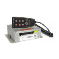
Qty Item
1 CP4688-10 10-Pin Terminal Block Plug
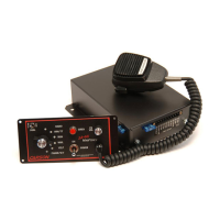
1 SC-1022-10CH Hand Control Assembly
1 VELCRO Strip Fastener
1 CP5208 Instruction Manual
1 CP5003 Hand Control Holster