Page 4 of 8 SC-1022-20 Installation Instructions
1/3/20 CP5208A
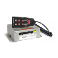
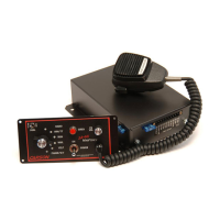
Hand Control: Choose a mounting location convenient to the operator and away from any air
bag deployment areas. Consider cable routing to amplifier. Mount the hand control with supplied
Hook and Loop tape (VELCRO). If the tape method is not preferred, the hand control may be
mounted several ways. A Holster (CP5003) to hold the Hand Control or a Hanger and Holder to
hold the Hand Control like a microphone (ED1865) are available accessories.
See PARTS and ACCESSORIES Section.
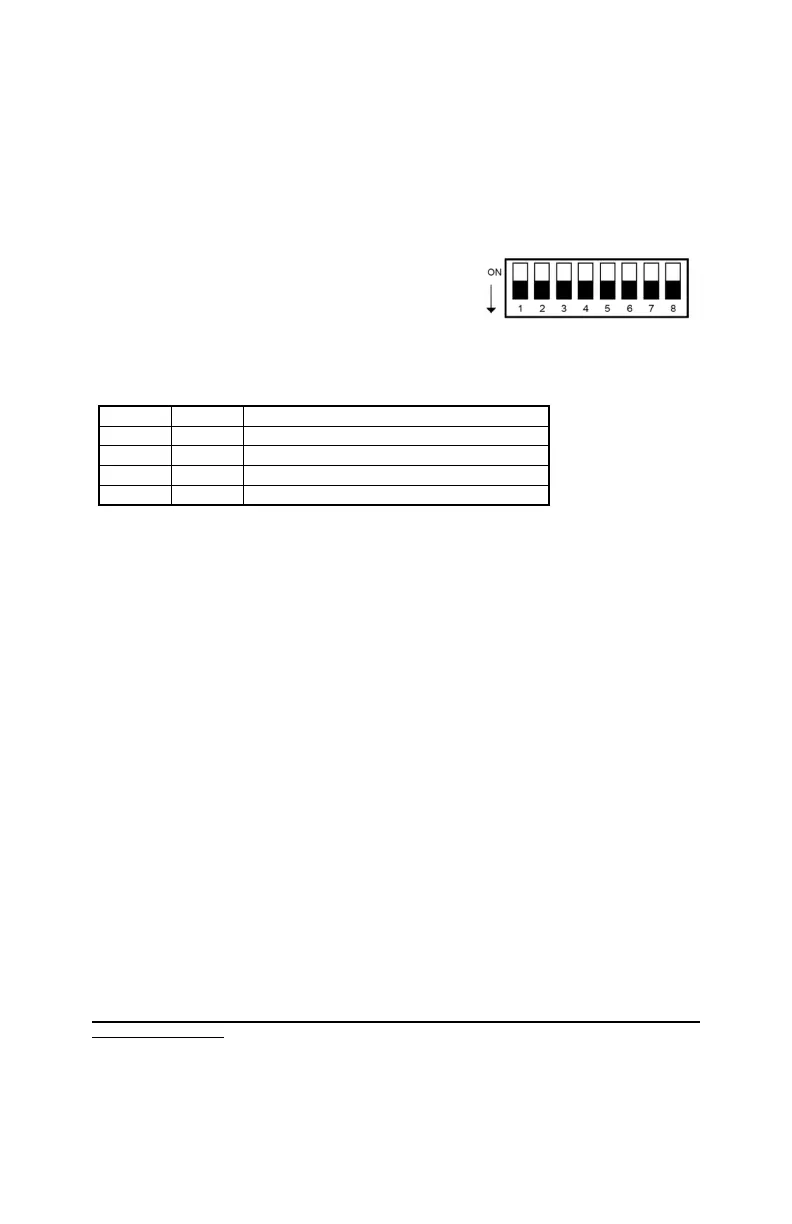
OPTION SWITCHES
An 8-position DIP switch on one side of the amplifier may
be changed to select various options.
Adjusting Option Switches - use a small screwdriver to
change switch settings.
The default setting is shown here. All switches are on.
SW-1 Auxiliary Input Polarity - The auxiliary input is normally activated with positive. Turn
switch OFF for negative activation.
SW-4 Two-Tone - Turn this switch OFF to replace Phaser with Two-Tone.
SW-5 Horn Enable - Turn this switch OFF to disable Horn tone. Horn replaced with Yelp.
SW-4 & 5 Tone Disable - All siren tones may be disabled except Manual, Wail and Yelp by turn-
ing OFF both switches. Mechanical will be replaced with Wail. Phaser and Horn will be replaced
with Yelp.
SW-6 Short Manual - The Manual siren tone will normally fall and die out when released. Turn
this switch OFF to have Manual stop immediately.
SW-7 Manual Wail - Turn this switch OFF for Manual Wail instead of Manual Mechanical when
pressing the MAN pushbutton.
SW-8 Mechanical Fall - Turn this switch OFF for a quicker mechanical tone fall time.
HORN RING CYCLER 2 (HRC2) - Turn OFF DIP SW-2 and SW-3 to enable this feature. Also
connect the auxiliary input to the horn ring or other switch. While the siren is in standby, tap the
horn ring to bring the unit out of standby into Mechanical tone. Repeatedly tapping the horn ring
will cycle through Mechanical, Wail, Yelp, and Phaser tones. Tapping the horn ring twice quickly
will stop the siren tones and return the unit to standby. Pressing and holding the horn ring will
produce Horn tone until released. Then the siren will return to its previous siren tone or standby.
ELECTRICAL CONNECTIONS
Electrical connections to the unit are made using terminal block plugs and screw terminals located
on the amplifier. Labels on the unit identify each terminal function. Install the plug on the unit
before wiring. If the unit needs service the plug can be easily removed without unwiring. The
power supply of the unit must be capable of delivering peak currents up to 50 amps for adequate
short circuit protection and reliable operation. The preferred source is directly at the vehicle bat-
tery. The amplifier is fused.
Attach leads by stripping 3/8”, inserting into plug and clamp by tightening screw. Make sure the
screw is tight and the wire can’t be pulled out.
Failure to adequately tighten the screw can result in improper operation or burning the
connector and wire.
Wire Size and Termination - The diagram shows the minimum wire size used for each connec-
tion, along with recommended lead color. If the wire is longer than 10 ft. use the next larger wire
size. Use only high quality crimp connectors for installation on the vehicle.
SW-2 SW-3 Auxiliary Tone in Standby
ON ON (Default) Produces Horn tone while activated.
OFF ON Manual control of Mechanical tone.
ON OFF Manual control of Wail tone.
OFF OFF Activates Horn Ring Cycler 2 (HRC2) function.