SC-1022-20 Installation Instructions Page 5 of 8
CP5208A 1/3/20
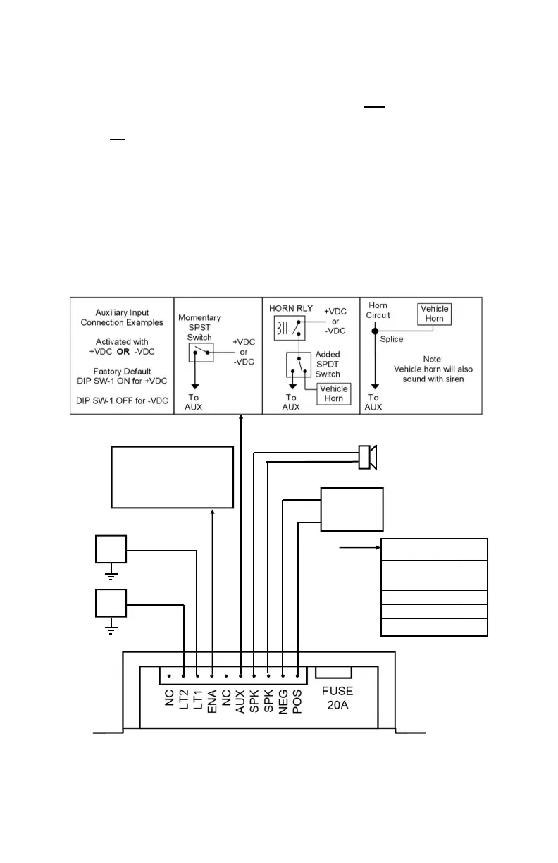
Enable Input Connection (ORG lead on wiring diagram) - This is NOT the same as the main
power connection. The enable input is like a power switch for the unit. When there is positive
power at this connection, the unit is powered up and ready to function. When power is removed,
the unit is not powered up and will not drain current from the battery. Connect to a positive circuit
controlled by the vehicle ignition switch, usually a terminal at the vehicle fuse panel. The required
current is low (15mA typ.).
Auxiliary Input Connection (Optional) - A momentary input typically connected to the horn ring
of the vehicle or other switch. See OPERATION section for auxiliary input functions.
NOTE: Permanent disconnection of the vehicle horn is NOT recommended.
The auxiliary input may be activated with positive or negative voltage. See Auxiliary Polarity
under OPTION SWITCHES section for proper activation polarity. Input current is 1 to 20 mA.
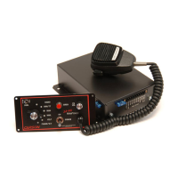
Hand Control Connection - Route cable and plug into RJ12 jack on amplifier.
#18G BRN
#18G BRN
BAT
-
+
RED
#16G BLK
RED (Positive Supply)
Recommended Wire Size
Load 1 + Load 2 +
8A for Amplifier
Amps
Gauge
5 - 10 #16
10 - 15 #14
Use next larger size if
longer than 10 ft.
AUX
#22G WHT
ENA
#22G ORG
Enable Input
(like an ON/OFF switch)
Connect to positive circuit
(fuse panel) controlled by
ignition or other switch
Load
1
Load
2
Gauge -
see table