Do you have a question about the Carver M400t and is the answer not in the manual?
201 watts RMS per channel into 8 ohms from 20Hz to 20kHz with .5% THD.
250W RMS/ch into 8 ohms @ 1kHz; 300W RMS/ch into 4 ohms; 500W RMS bridged.
Greater than 100dB down, IHF A weighted; commutation noise < non-linear distortion.
.05% SMPTE.
Unmeasurable.
+0 - 3dB 1Hz - 250kHz at 1 watt (excluding filter).
Greater than 200.
Input: +0-3dB below 40kHz. Output: +/- 3dB, 0Hz-40kHz.
Tracking: +/- 1 LED Digit. Ballistics: Peak responding, 1ms attack, .5s decay.
Keep original packing materials and record the unit's serial number for reference.
Locate on a smooth surface, make connections before plugging in AC power cord.
Use good quality wire; ensure correct phasing for optimal sound.
Check system compatibility; connect ground wire to 'chassis' terminal and reverse wires for phase.
Use 'Y' connector for input, connect speaker leads to outer terminals for 500W RMS output.
Connect to preamp outlet; use heavy duty cord if needed; observe outlet rating.
Double-check connections before powering on; never change connections with AC cord plugged in.
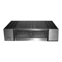
Serves as VU level indicator and fault indicator, strobing on fault conditions.
Main fuse is AGC 15; replace with same value only; consider separate fusing for speakers.
Unit generates heat under high power; ensure good ventilation around and beneath the unit.
Digitally controlled computer monitors voice coil temp/stresses to protect speakers.
Avoid shorting terminals, moisture, dust, dropping; clean with soft cloth; check system for issues.
Contact dealer or factory for service; do not disassemble unit yourself.
A 60 Hz sound may occur; loosen rubber shock mounts if audible.
Requires different test procedures than conventional amps due to unique technology.