Do you have a question about the CAS SC-25P and is the answer not in the manual?
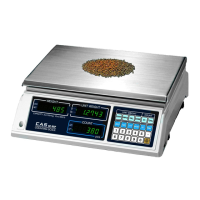
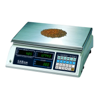
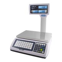
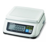
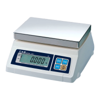
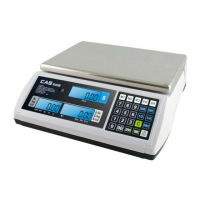
Introduction to the CAS scale, highlighting its reliability and performance features.
Essential precautions for scale installation, operation, and environmental conditions.
Detailed technical specifications for different SC series models, including capacity and resolution.
Illustrated step-by-step guide for the sealing procedure of the scale.
Procedures for general span calibration, including setting mode, zero point, and span adjustment.
Steps to exit calibration mode and return the scale to its normal operating state.
Detailed instructions for replacing the load cell and correcting eccentricity.
Guide for replacing the analog circuit board and its calibration.
Instructions for replacing the keyboard, including key testing and return to normal mode.
Details about the transformer, including lead wire quality and length specifications.
Schematic diagram illustrating the main circuit of the SC series scale.
Circuit diagram specifically for the display unit of the SC series scale.
Comprehensive wiring diagram showing connections between different components and PCBs.
Diagram showing the physical location of electronic components on the PCB.
Protocols and agreements for the CAS standard serial interface (RS-232C), covering communication parameters, wire connections, and data protocols.
An exploded view diagram showing the assembly of the scale's components.
A comprehensive list of all parts used in the SC series, including part numbers and specifications.
| Capacity | 25 kg |
|---|---|
| Display | LCD |
| Auto Power Off | Yes |
| Units | kg, lb |
| Power Supply | Battery or AC adapter |
| Power | 4 x AA batteries |