CHAPTER 4
26 Case IH 3230/3240/3320/3330/3340 & 4420/4430/4440, Model Year 2010 & Newer ISO AutoBoom® Installation Manual
MOUNT THE BOOM SENSORS
FIGURE 2. Sensor Installed on Mounting Bracket
1. Install the left and right ultrasonic sensors (P/N 063-0130-012 and 063-0130-014) on the ultrasonic sensor
mounting brackets (P/N 107-0172-501) using four 3/8”-16 x 1-1/4” hex bolts (P/N 311-0054-081) and four 3/8”-16
zinc flanged lock nuts (P/N 312-1001-164) per sensor.
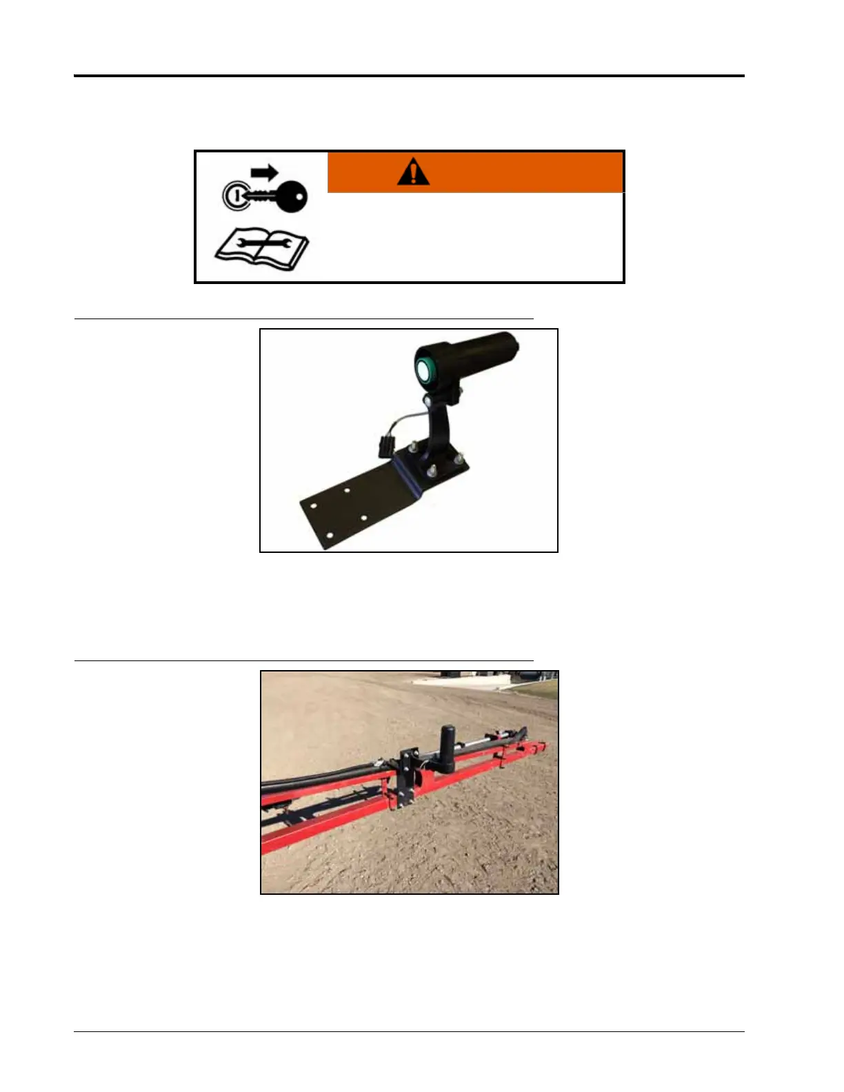
FIGURE 3. Left Boom Sensor Installed
2. Mount the left boom sensor assembly on the front of the left-outer boom section using two 2-1/16” W x 3” L x
3/8” thread U-bolts (P/N 107-0171-609) and four 3/8”-16 zinc flanged lock nuts (P/N 312-1001-164).
3. Mount the right boom sensor assembly on the front of the right-outer boom section using two 2-1/16” W x 3” L
x 3/8” thread U-bolts (P/N 107-0171-609) and four 3/8”-16 zinc flanged lock nuts (P/N 312-1001-164).
WARNING
The machine must remain stationary and
switched off, with the boom unfolded and
supported, during installation or maintenance.