HYDRAULIC,PNEUMATIC,ELECTRICAL,ELECTRONICSYSTEMS-PRIMARYHYDRAULICPOWERSYSTEM
Options/Congurations
Transmission
HydraulicCVT
Table1
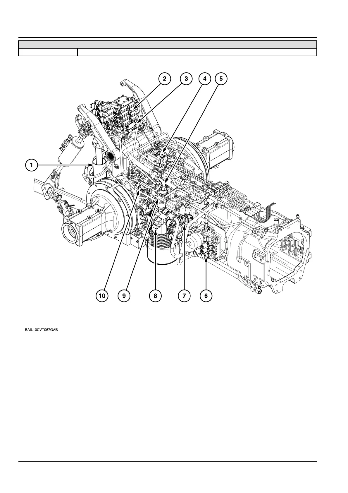
BAIL10CVT067GAB1
Mainhydrauliccomponents
1.Hydraulicliftcylinder
2.Hydraulicremotevalves
3.Electronicdraftcontrolvalve4.Distributionmanifold
5.Highpressurefeedpipe
6.Hydrostatcontrolvalve
7.Gearpump8.Mainsuctionlter
9.Variabledisplacementpump10.Trailerbrakevalve
Thehighpressurecircuitisofthe`ClosedCentreLoadSensing'designonalltractormodeloptionsfedbyaVariable
DisplacementPump.
Figure2showsthevariabledisplacementpump(1)andsuctionlterassembly(2).
Whentheoiliscoldandpressuredifferentialacrosstheoilcoolerishigherthan5°C(41.0°F)thecoolerby-pass
valvelocatedinthechargepumpwilloperatetoensurethatadequateowtothelubricationcircuitismaintained.This
featureofdivertingoilfromthecoolerassistsinaidingarapidwarmupofoilincoldweatherconditions.
84479138A06/06/2011
A.10.A/18