HYDRAULIC,PNEUMATIC,ELECTRICAL,ELECTRONICSYSTEMS-PRIMARYHYDRAULICPOWERSYSTEM
BAIL10CVT063FAB18
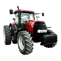
Fronthydraulicpowerlift
CLOSEDCENTRELOADSENSINGHIGHPRESSUREHYDRAULICCIRCUIT
Theprincipalofoperationoftheclosedcentreloadsensinghighpressurehydrauliccircuitwithvariableowpiston
pumpistosupplyoilowondemand.Italsoenablessimultaneousoperationofthetrailerbrakes,hydrauliclift,
remotecontrolvalveassembliesandfrontaxlesuspensionwheretted.Theloadsensingvariableowpistonpump
offerssignicantbenetsinreducingtheenginepowerlossthatoccursinopencentresystemswhereahighvolume
ofoil,oftenfarinexcessofdemand,iscontinuouslypumpedroundthehydrauliccircuitevenwhentheyarenotbeing
operated.
Axeddisplacementpump(ChargePump)servesasaninitialdisplacementpumpforthevariabledisplacementpump
.Thevariabledisplacementpumprstofallsuppliesoiltothetrailerbrakevalve(wheretted),theremotevalves
andelectronicdraftcontrolvalveandapilotoilsupplywithlowerpriority.Thehighestloadpressureisindicatedto
theowandcompensatingvalveonthepumpviatheloadsensingline.Theowandcompensatorvalvecontrols
thepumppressureinsuchawaythatitalwaysexceedsthehighestloadpressurebyapre-setdifference.Apriority
valveforlowpressurecircuitdemandislocatedinthebottomsubplateoftheremotevalvestack.Tractorsttedwith
Electro-hydraulicremotevalvesalsohavehighpressureoilsuppliedfromthevariabledisplacementpumptothetop
plateoftheremotevalvestack.Theoilpassesthroughthetopplateviaasmalllterandapressurelimitingvalve(
20-22Bar).Theoilisthendirectedtothepilotoilsupplyoftheelectro-hydrauliccontrolvalve.
Themainlter(1)andthechargelter(2)Figure19areinstalledontractorswithvariabledisplacementpump(CCLS
system).
1.MainIntake(Suction)lter
2.Chargelter
3.Hydrostatlter
84479138A06/06/2011
A.10.A/24