SOLENOID SWITCH CHECK AND SPECIFICATIONS
Delco-Remy Case Amperage Draw
:-.Jo.
No. both windings
1498
A21-±81 2.1 - 2.3
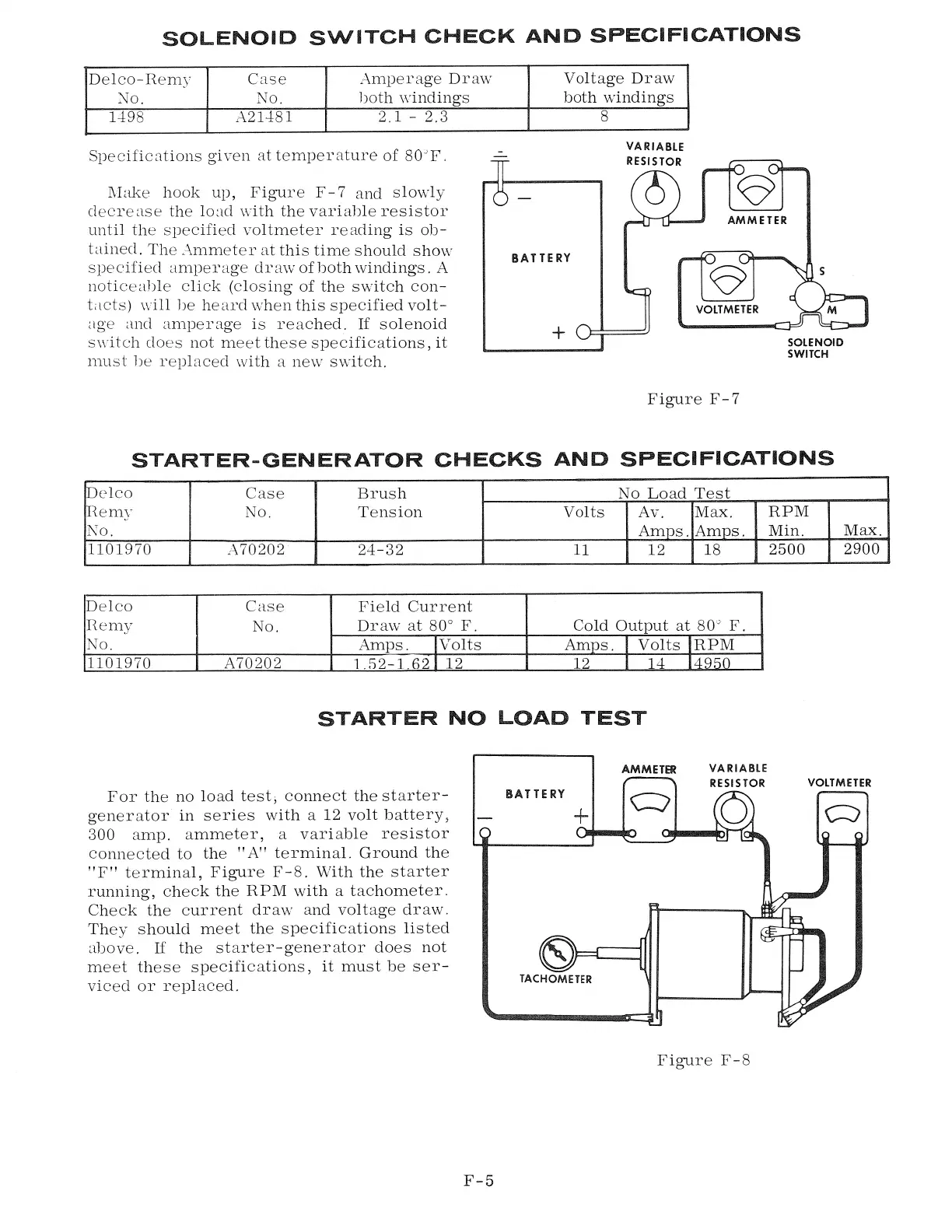
Specifications given at temperature of 80JF.
l\Iake hook up, Figure F- 7 and slo,vly
decrease the load vvith the variable resistor
until the specified voltmeter reading is ob-
tained. The A.mmeter at this time should show
specified amperage draw of both windings. A
noticeable click (closing of the switch con-
t.lets) will be heard when this specified volt-
age and amperage is reached.
If
solenoid
switch does not meet these specifications, it
must be replaced with a ne,v switch.
Voltage Dr aw
both windings
8
VARIABLE
RESISTOR
AMMETER
BATTERY
VOLTMETER
+
Figure F-7
SOLENOID
SWITCH
STARTER-GENERATOR CHECKS AND SPECIFICATIONS
Delco
Case
Brush
No Load Test
Remy
No. Tension
Volts
Av. Max.
RPM
1\0,
Amps, Amps,
Min.
1101970
A70202 24-32
11
12
18
2500
Delco
Case
Field Current
Remy
No.
Draw at 80° F.
Cold Output at 80" F.
No.
Amps.
!Volts
Amps.
I
Volts 1RPM
1101970 A70202
1.52-1.62
I
12 12
I
14 14950
STARTER NO LOAD TEST
AMMETER
Max.
2900
VARIABLE
RESISTOR VOLTMETER
For the no load test, connect the starter-
generator in series with a 12 volt battery,
300 amp. ammeter, a variable resistor
connected to the "A" terminal. Ground the
"F" terminal, Figure F-8. With the starter
running, check the RPM with a tachometer.
Check the current draw and voltage draw.
They should meet the specifications listed
above.
If
the starter-generator does not
meet these specifications, it must be ser-
viced or replaced.
F-5
BATTERY
+
TACHOMETER
c::;
Figure F-8