GENERATOR OUT-PUT CHECK
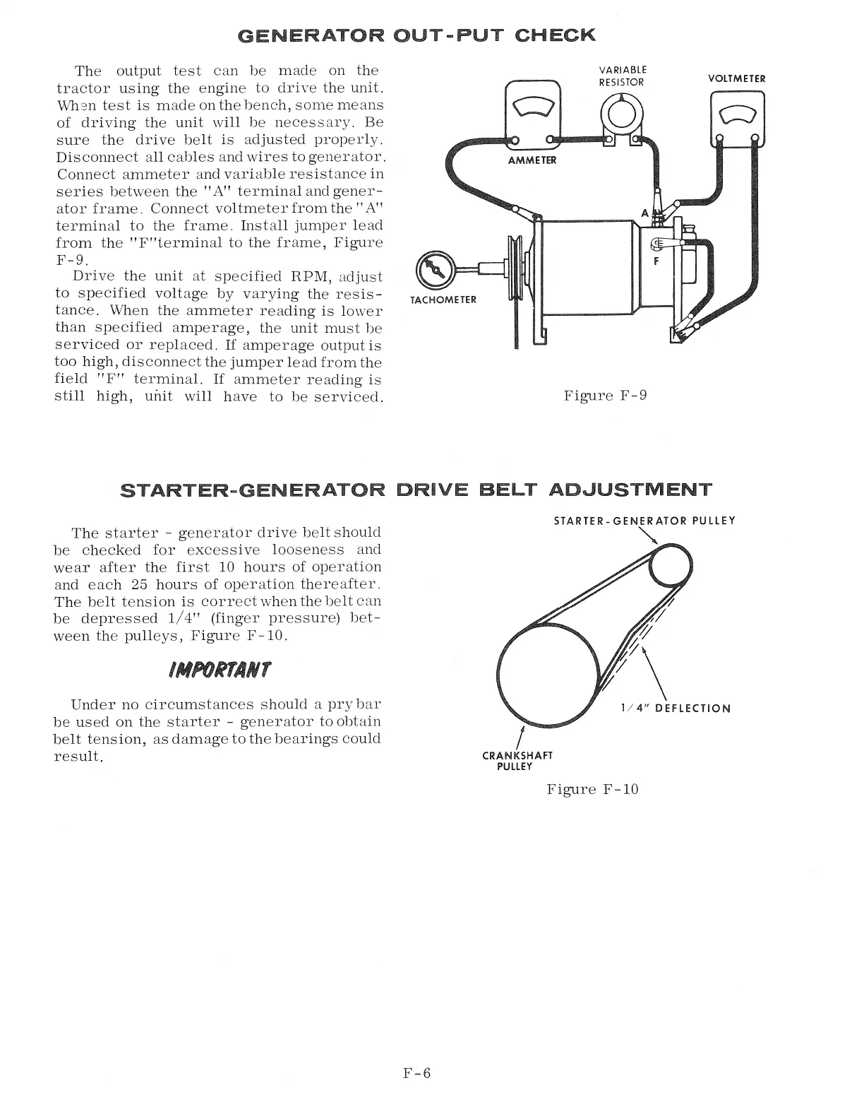
The output test can be made on the
tractor using the engine to drive the unit.
Wh2n test is made on the bench, some means
of driving the unit will be necessary. Be
sure the drive belt is adjusted properly.
Disconnect all cables and wires to generator.
Connect ammeter and variable resistance in
series between the "A" terminal and gener-
ator frame. Connect voltmeter from the"
A"
terminal to the frame. Install jumper lead
from the "F"terminal to the frame, Figure
F-9.
Drive the unit at specified RPM, adjust
to specified voltage by varying the resis-
tance. When the ammeter reading is lower
than specified amperage, the unit must be
serviced or replaced.
If
amperage output is
too high, disconnect the jumper lead from the
field "F" terminal.
If
ammeter reading is
still high, unit will have to be serviced.
TACHOMETER
VARIABLE
RESISTOR
Figure F-9
VOLTMETER
STARTER-GENERATOR DRIVE BELT ADJUSTMENT
The starter - generator drive belt should
be checked for excessive looseness and
wear after the first 10 hours of operation
and each
25
hours of operation thereafter.
The belt tension is correct when the belt can
be depressed 1/ 4" (finger pressure) bet-
ween the pulleys, Figure F-10.
IMPOINANT
Under no circumstances should a pry bar
be used on the starter - generator to obtain
belt tension, as damage to the bearings could
result.
F-6
I
CRANKSHAFT
PULLEY
STARTER- GENERATOR PULLEY
"
1/4" DEFLECTION
Figure F-10