SECTION 58 - ATTACHMENT/HEADERS - CHAPTER 2
58-6
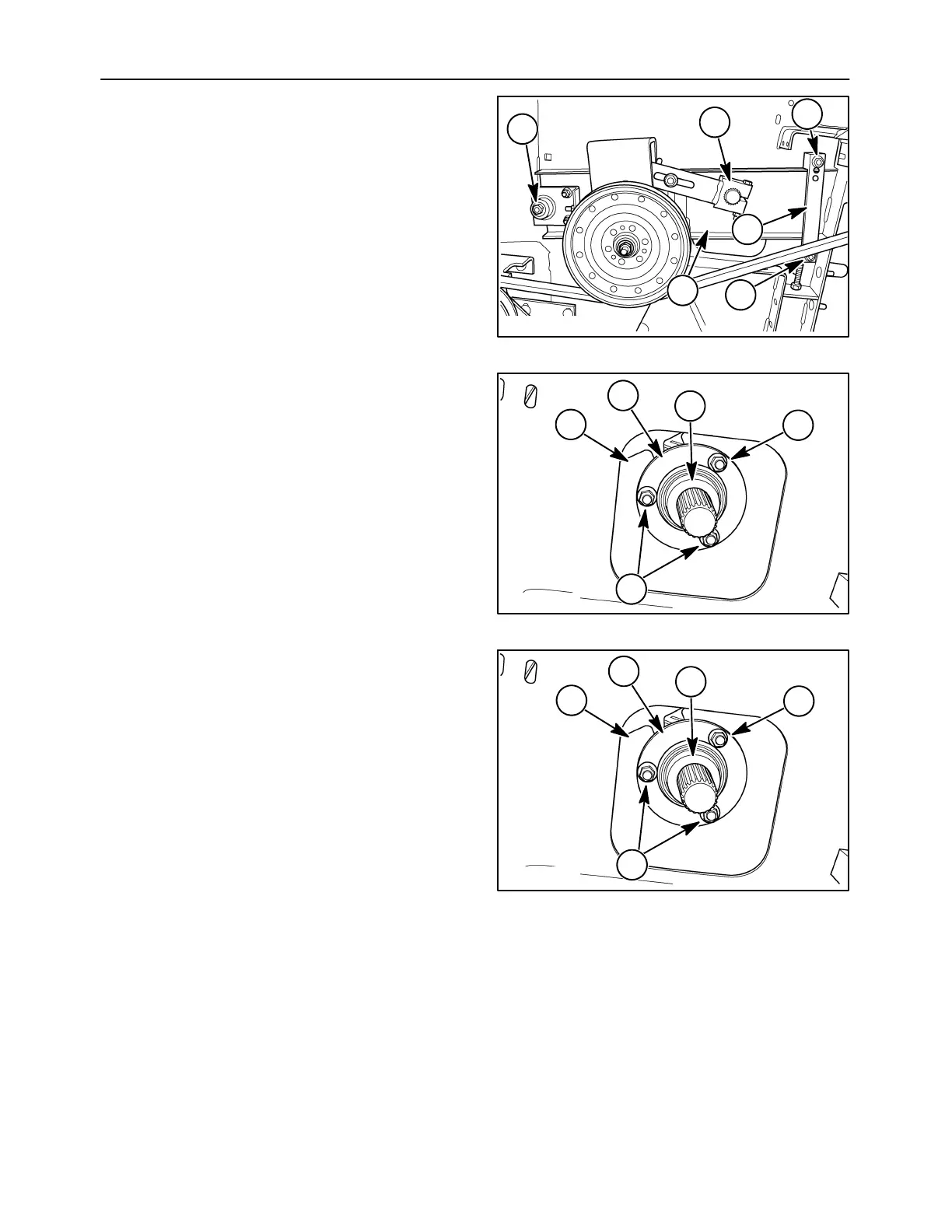
13. Match mark the adjusting lever, 1, to the auger
shaft. Slide the lever from the shaft. Remove
nuts, 2, and remove strip, 3. Pull channel, 4, from
the head.
10007691
1
2
2
2
3
4
13
14. Match mark the locking collar, 1, to the bearing,
2, to the frame, 3. Remove nuts, 4, and slide the
shaft assembly from the auger.
15. Carefully lift the auger from the head and store in
a suitable location.
10008312
4
4
1
2
3
14
AUGER INSTALLATION
1. Lower the auger into the head so that the drive
end is positioned on the left hand side of the unit.
2. Lineup the match marks between the locking
collar, 1, bearing, 2, and frame, 3. Insert the shaft
assembly into the auger. Attach the bearing to
the auger using three carriage bolts and nuts, 4.
10008312
4
4
1
2
3
15