SECTION 58 - ATTACHMENT/HEADERS - CHAPTER 2
58-18
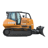
5. Match mark the adjusting lever, 1, to the auger
shaft. Slide the lever from the shaft. Remove
nuts, 2, and remove strip, 3. Pull channel, 4, from
the head.
10007691
1
2
2
2
3
4
44
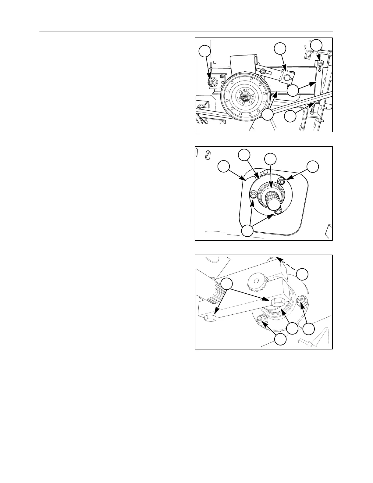
6. Match mark the locking collar, 1, to the bearing,
2, to the frame, 3. Remove nuts, 4, and slide the
shaft assembly from the auger.
10008312
4
4
1
2
3
45
NOTE: The bearing locking collars do not need to be
disengaged.
7. Remove the bearing mounting hardware,
disengage the clamp blocks and lift out the shafts
until the affected shaft can be accessed.
10008319
1
3
2
1
1
46
 Loading...