SECTION 58 - ATTACHMENT/HEADERS - CHAPTER 3
58-4
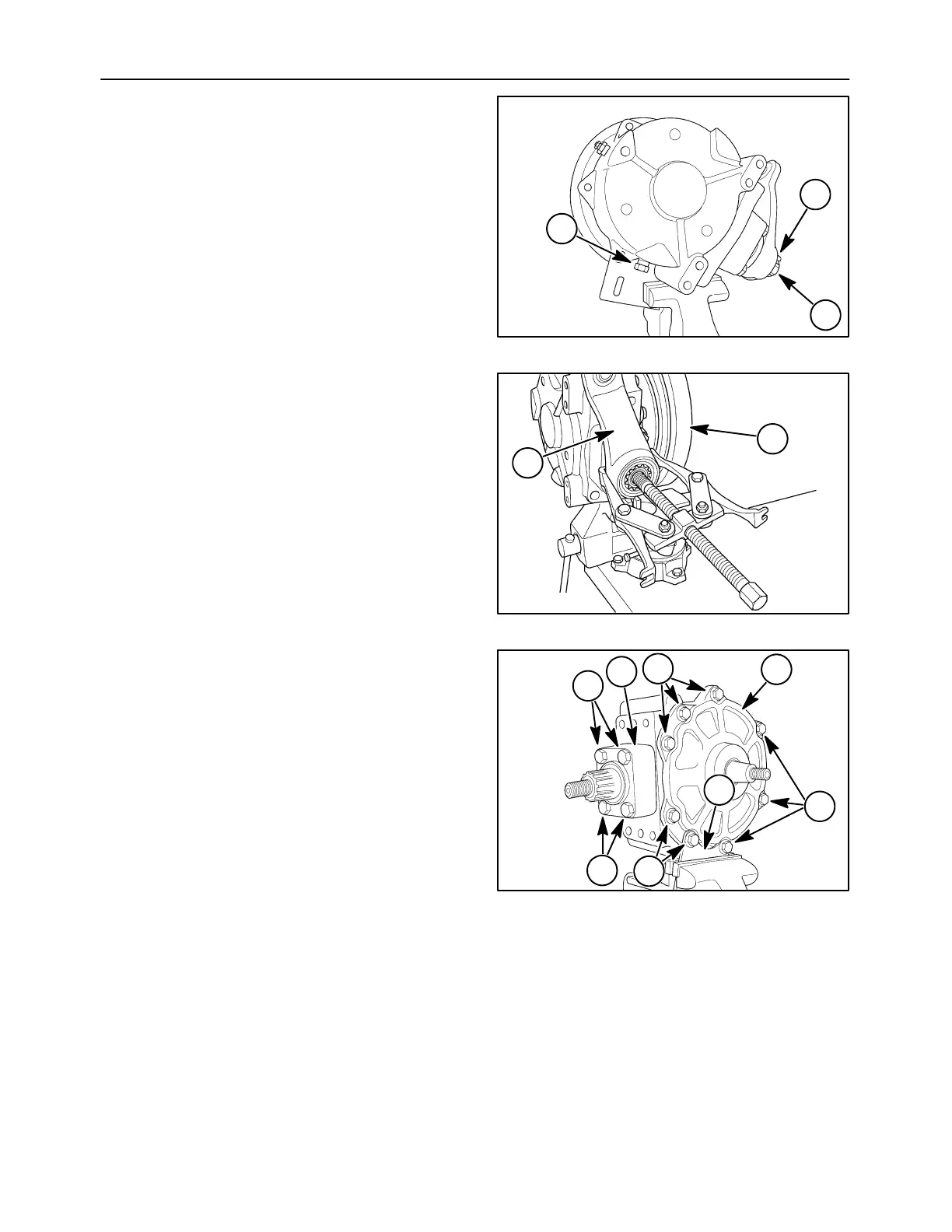
WOBBLE BOX DISASSEMBLY
1. Secure the box in a vise and drain the oil from the
gearbox at 1.
2. Bend the tabs of the locking plate, 2, away and
remove the nut, 3, from the knife arm shaft.
IMPORTANT: Notice the timing marks on the knife
arm and spline shaft. These marks must be lined up
during assembly. If no timing marks are present,
mark the knife arm and shaft so the arm can be
installed into its original position.
10007632
3
1
2
6
NOTE: The knife arm shaft is tapered. Heat may
have to be applied to the knife arm during removal.
3. Attach a puller to the knife arm, 1, and remove it
from the shaft.
NOTE: The drive sheave shaft is tapered. Heat may
have to be applied to the sheave during removal.
4. Remove the drive sheave, 2, from the wobble
box. Take the key from the shaft key way and
store in a suitable location.
10007633
2
1
7
5. Mark the orientation of the lower bearing
housing, 1, in relation to the wobble box casing.
Remove cap screws, 2, and remove the lower
bearing housing.
6. Mark the orientation of the side cover, 3, in
relation to the wobble box casing. Loosen the
eight cap screws, 4. Remove the wobble box
from the vise and set it on a firm surface. Remove
the eight cap screws previously loosened and lift
off the side cover, and frame brace, 5.
10007634
3
5
2
2
1
4
4
4
8
 Loading...