SECTION 58 - ATTACHMENT/HEADERS - CHAPTER 3
58-12
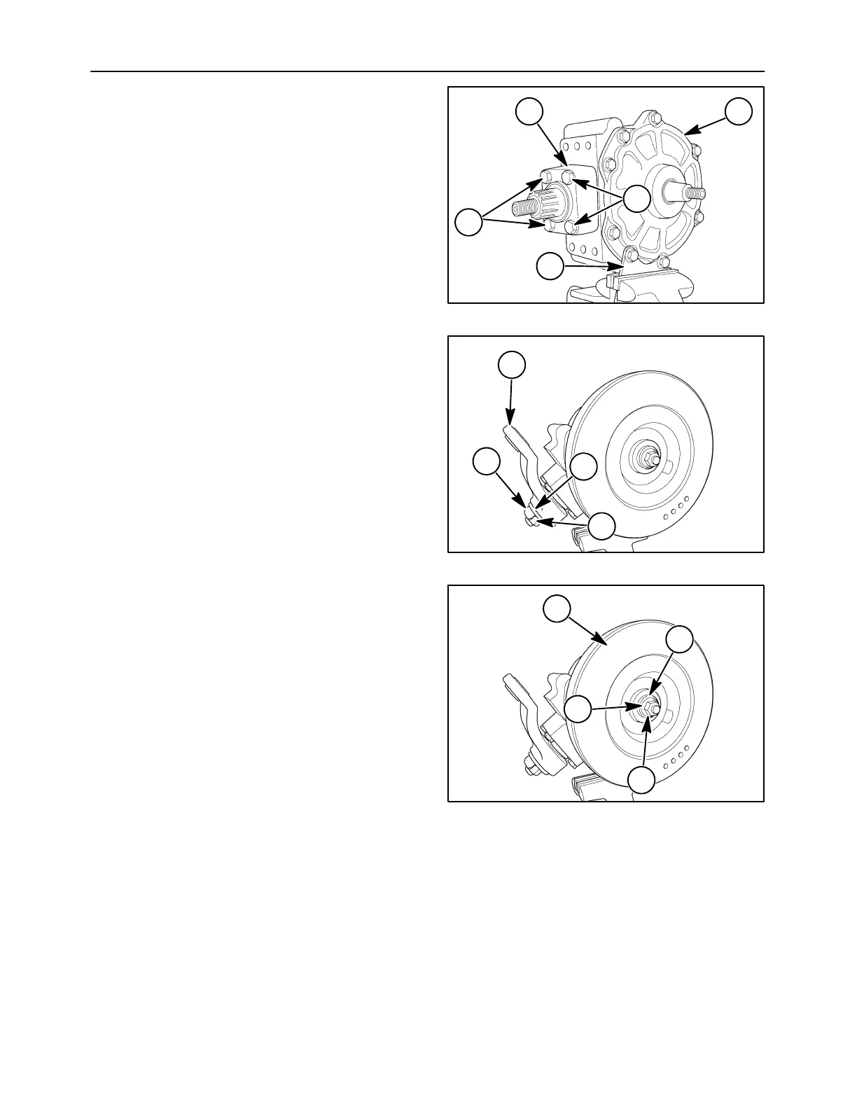
11. Set the cover, 1, and mounting frame, 2, into
place. Secure with the eight cap screws,
tightening evenly and crosswise.
12. Apply Loctite 515 to the lower bearing housing
cap screws, 3. Attach the bearing housing, 4, to
the gearbox casing with the four cap screws.
Torque the housing cap screws to 100 N⋅m (74 ft.
lbs.).
10007634
1
2
4
3
3
29
13. Position the knife arm, 1, onto the spline shaft
referencing the alignment marks. Slide washer,
2, and lock tab, 3, onto the shaft. Install nut, 4,
onto the knife arm shaft and tighten securely.
Bend up the lock tab to hold the nut in place.
10007649
2
1
3
4
30
14. Install the drive sheave, 1, onto the gearbox
shaft. Strike the sheave several times with a
mallet to seat it onto the tapered shaft. Slide a flat
washer, 2, and lock washer, 3, onto the shaft.
Install nut, 4, onto the end and tighten securely.
2
1
3
4
10007649
31
 Loading...