2001-28
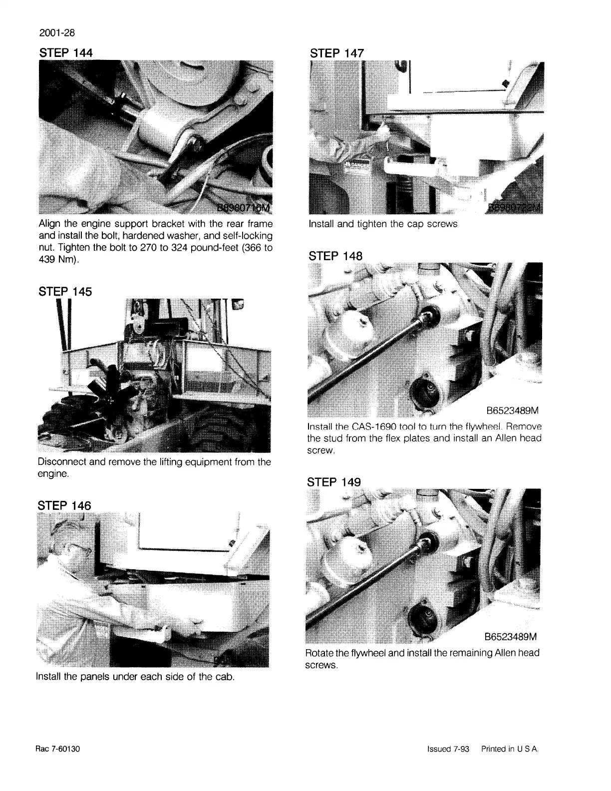
STEP 144
Align the engine support bracket with the rear frame
and install the bolt, hardened washer, and self-locking
nut. Tighten the bolt to 270 to 324 pound-feet (366 to
439 Nm).
STEP 145
Disconnect and remove the lifting equipment from the
engine.
STEP 146
4
-----_..,;;~/··
Install the panels under each side of the cab.
Rae
7-60130
STEP 147
Install and tighten the cap screws
STEP 148
B6523489M
Install the CAS-1690 tool to turn the flywheel. Remove
the stud from the flex plates and install
an
Allen head
screw.
STEP 149
B6523489M
Rotate the flywheel and install the remaining Allen head
screws.
Issued
7-93
Printed
in
US
A.