Do you have a question about the Casio ap-24 and is the answer not in the manual?
Detailed mapping of keyboard keys to matrix signals.
Describes the matrix configuration for control buttons.
Layout and details of the sub processing circuit board.
Layout and details of the power supply circuit board.
Layout and details of the jack connection circuit board.
Layout and details of the console control circuit board.
Layout and details of the LED indicator circuit board.
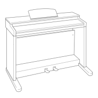
Steps to remove the piano unit and pedal from the stand.
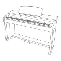
Procedures for removing the piano's top board and keyboard cover.
Detailed process for detaching the main keyboard assembly from the piano.
Instructions for removing the printed circuit board associated with the keys.
Steps to remove various PCBs, transformer, speakers, and connectors.
Connecting power/pedal and initiating the diagnostic mode.
Covers RAM, ROM, and LED checks for system integrity.
Verifying functionality of buttons and pedals through specific test sequences.
Testing headphone output and MIDI IN/OUT connectivity.
Verifying the firmware version and LED status.
Electrical diagram for the main control board.
Wiring diagram for the pedal unit.
Electrical diagram for the sub processing board.
Wiring diagram for the jack connections.
Electrical diagram for the console control board.
Wiring diagram for the LED indicator board.
Electrical diagram for the power supply unit.
Electrical diagram for a specific keyboard PCB.
Electrical diagram for another keyboard PCB.
Electrical diagram for a third keyboard PCB.
List of components for the main printed circuit board.
Component list for the PSA (Processing/Signal Amplifier) PCB.
Component list for PS2A and PS3A PCBs.
List of parts for the main chassis and casing.
Component list for the keyboard mechanism and related parts.
List of parts for the piano stand and optional accessories.
| MIDI | Yes |
|---|---|
| Pedal Input | Yes |
| Sound Source | AHL |
| Polyphony (Maximum) | 48 |
| Digital Effects | 10 Reverb, 5 Chorus |
| Other Functions | Layer, Split |
| Tuning Control | Yes |
| Speakers | 2 x 12 cm |
| Input/Output Terminals | Headphone |
| Touch Response | 3 levels |
| Tempo Range | 30 to 255 |
| Power Supply | AC Adaptor |