— 8 —
DAC (UPD6376CX)
UPD6376CX is a two-channel 16-bit Digital to Analog Convertor consisting of resistor string, output
amplifier and zero offset circuit.
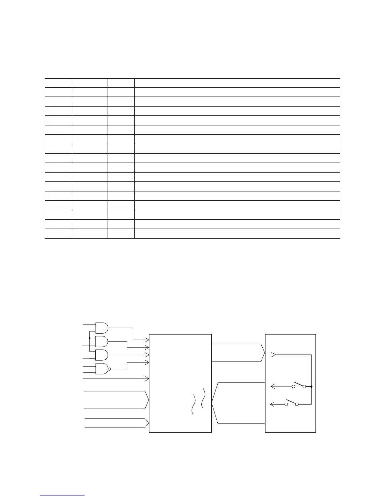
Key Touch LSI (HG52E35P)
By counting the time between first-key input signal FI and second-key SI from the keyboard unit, the key
touch LSI detects key velocity of 256-step. Then the LSI sends the CPU the note number and its velocity
data.
CRDB
CWRB
CKI
CCSB
RESB
CD0
CD7
CA0 ~ CA2
First contact
Second contact
KC0
KC7
FI0
FI7
SI0
SI7
Key input signal
Key scan signal
~
Data bus
Address bus
Key touch LSI
LSI106
HG52E35P
Keyboard
FI
SI
KC
RD
WR
APO
A12
A14
CLOCK
RESET
Pin No. Terminal In/Out Function
1 SEL In Mode selection terminal. Connected to ground.
2 D.GND In Ground (0 V) source for internal digital circuit
3 NC Not used
4 DVDD In +5 V source for internal digital circuit
5 A.GND In Ground (0 V) source for internal analog circuit
6 R.OUT Out Right channel sound waveform output
7 A.VDD In +5 V source for internal analog circuit
8 A.VDD In +5 V source for internal analog circuit
9 R.REF In Reference voltage terminal. Connected to a capacitor.
10 L.REF In Reference voltage terminal. Connected to a capacitor.
11 L.OUT Out Left channel sound waveform output
12 A.GND In Ground (0 V) source for internal analog circuit
13 LRCK In Word clock (L/R separation signal) input.
14 LRSEL In Not used. Connected to ground.
15 SI In Sound data input
16 CLK In Bit clock input